- DLP 3D Printed Ultra-detail Resin Arm Garage Kit
- SLA 3D Printed Suitcase Prototype with Silk-screen Logos
Gallery
About Project
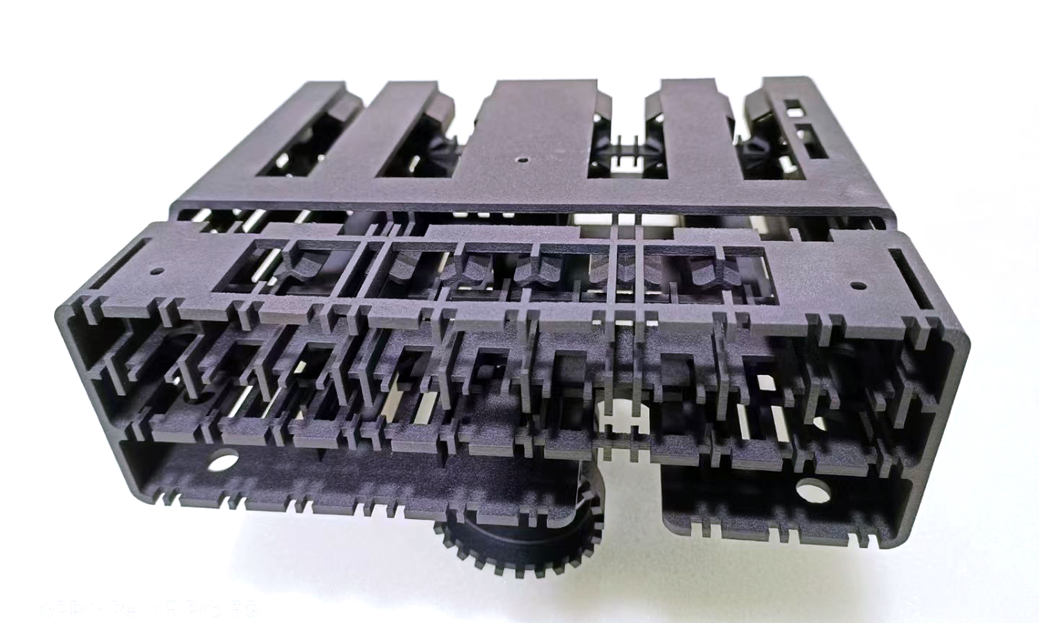
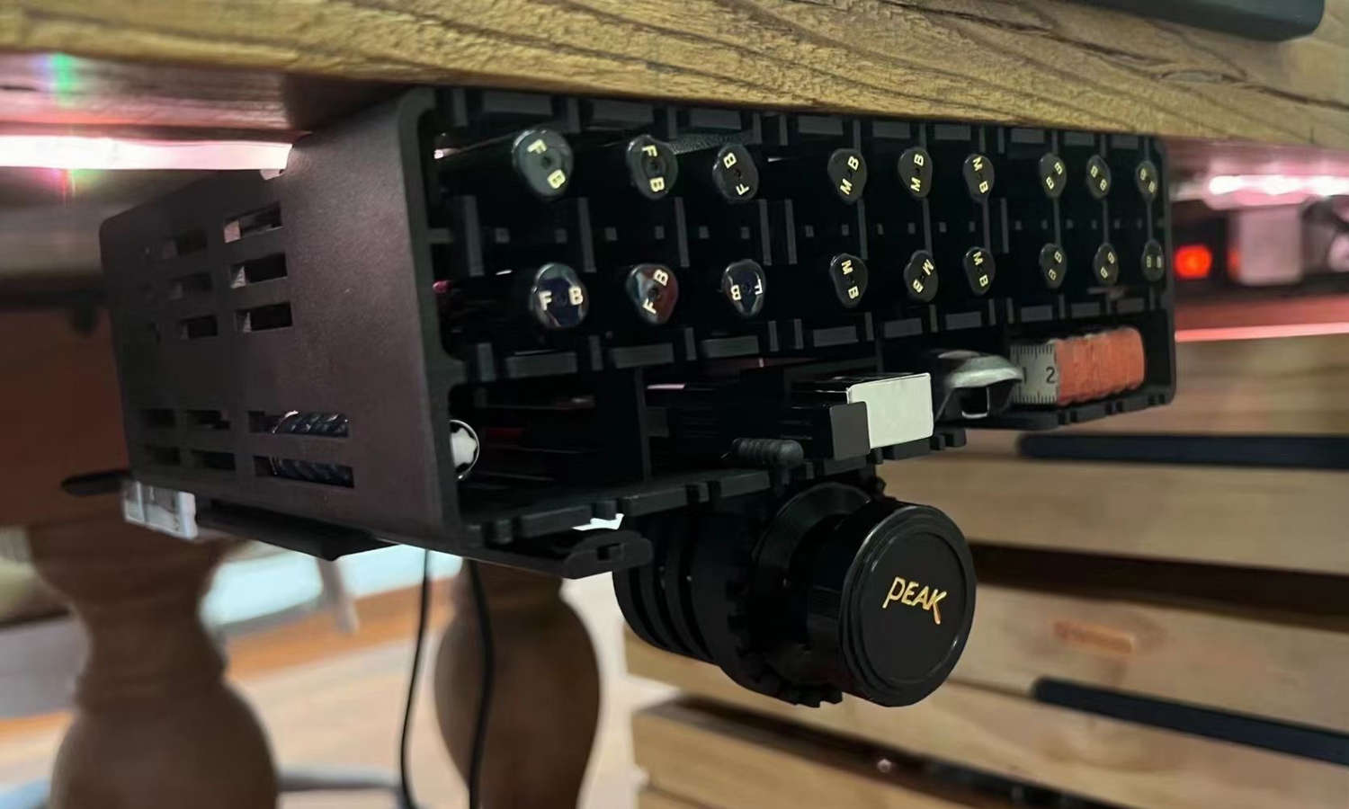
Are you looking for a versatile and durable camera rig mounting system that can fit your needs? If so, you might be interested in the 3D printed camera rig, a product designed and prototyped by FacFox, a leading company in 3D printing and prototyping services for the electronics industry.
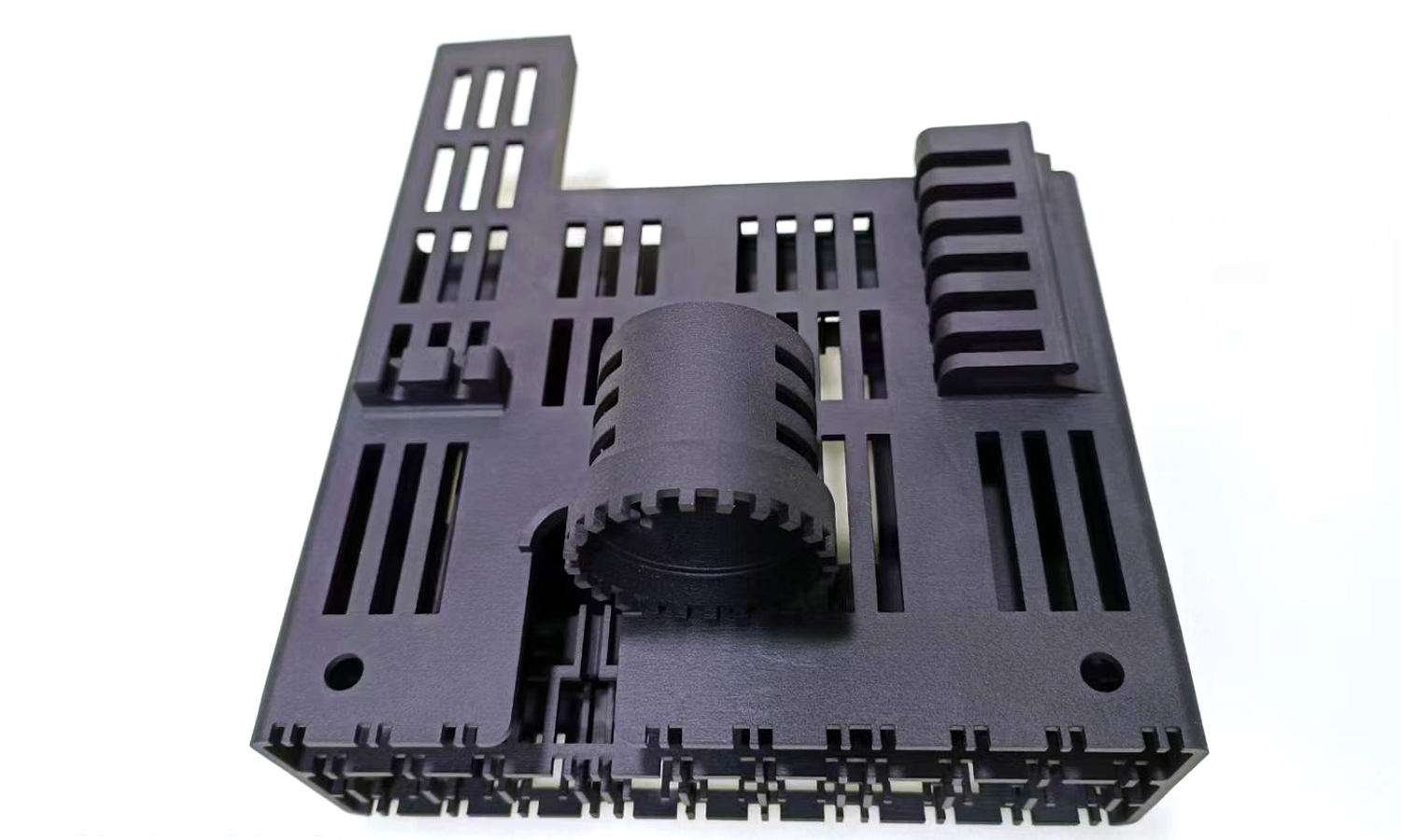
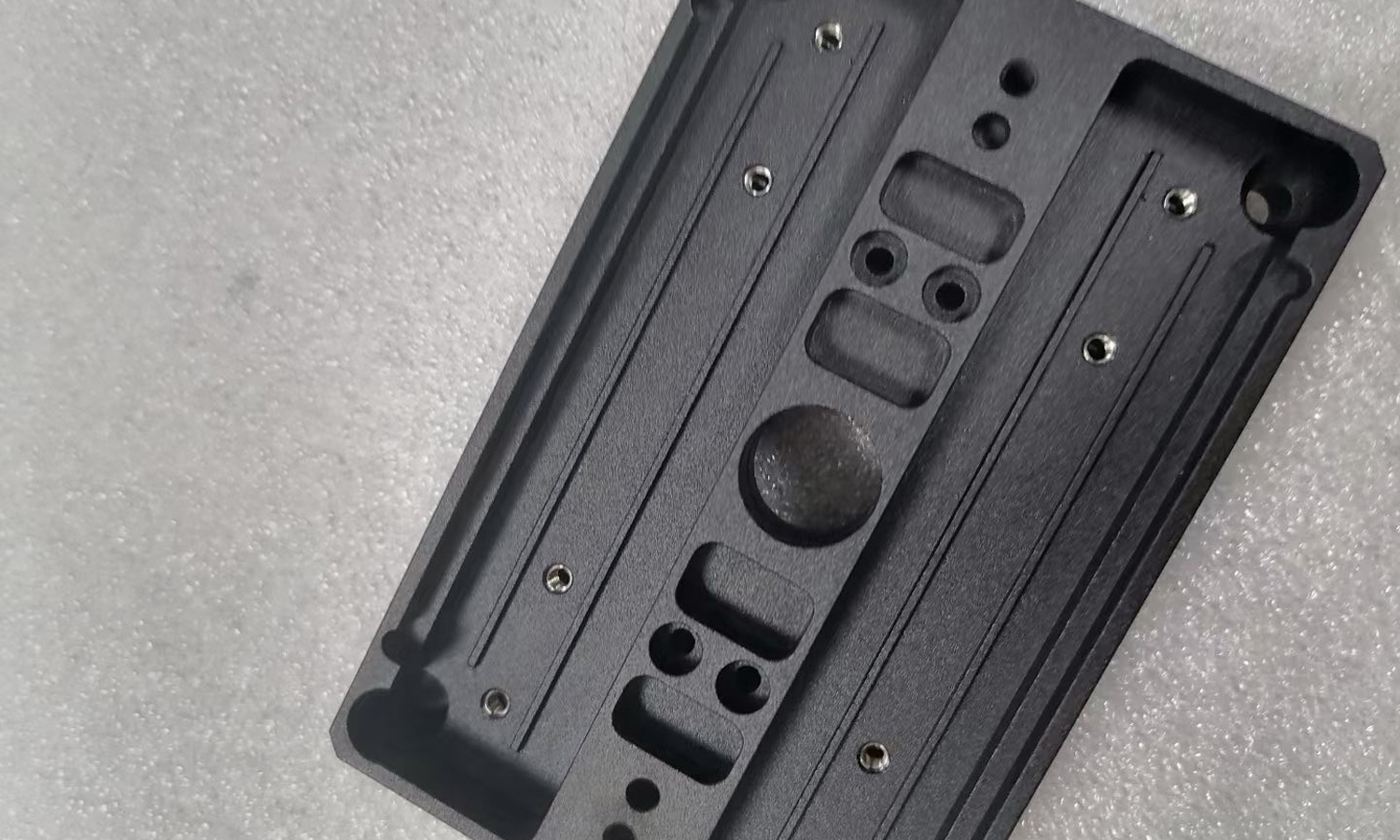
The nylon mounting system baseplate is a baseplate that can be mounted under a table and hung a camera lens. It has many hollowed cells that can accommodate aluminum alloy rods of different lengths. It also has some small holes that can be used to secure the baseplate with bolts. The baseplate is made of nylon, a strong and flexible material that can withstand high temperatures and pressures. The baseplate is printed using MJF (Multi Jet Fusion) technology, a 3D printing process that creates high-quality and detailed parts with smooth surfaces and fine details.
The MJF 3D printed nylon camera rig is a perfect example of how FacFox can help you create custom and innovative solutions for your electronics projects. FacFox offers a wide range of 3D printing and prototyping services, such as FDM, SLA, SLS, DMLS, CNC machining, injection molding, vacuum casting, and more. FacFox can handle any design, size, and quantity of your orders, and deliver them fast and reliably. FacFox also provides professional design and engineering support, as well as quality assurance and testing.
If you want to learn more about the MJF 3D Printed Nylon Camera Rig Mounting System Baseplate, or any other products and services offered by FacFox, please visit their website facfox.com or contact them directly. You can also check out their portfolio of previous projects and customer reviews. FacFox is your trusted partner for 3D printing and prototyping services for the electronics industry.
Solution
- Step 1: A 3D model of the baseplate was created using a CAD software and uploaded to the HP 3D printer software. The software optimized the model for printing and packed it efficiently in the build chamber.
- Step 2: a build unit was inserted into the 3D printer. The build unit contained a bed of nylon powder, which was spread over the print area by a recoater.
- Step 3: an inkjet array deposited fusing and detailing agents on the powder bed, according to the dimensions and boundaries of the baseplate. The fusing agent marked the areas that needed to be solidified, while the detailing agent improved the surface finish and resolution of the part.
- Step 4: the print area was exposed to infrared light, which heated and fused the powder where the fusing agent was applied. The rest of the powder remained loose and acted as a support material.
- Step 5: This process was repeated layer by layer, until the baseplate was fully printed. The baseplate had many hollowed cells and small holes that allowed for the insertion of aluminum alloy rods and bolts.
- Step 6: The build unit was removed from the 3D printer and transferred to a processing station, where the baseplate was cooled down and separated from the excess powder. The powder was recycled for future use, while the baseplate was cleaned and inspected for quality.
