Material Metal
Quantity 1 pcs
Price Range $1-100
Lead Time 3 workdays
Gallery
About Project
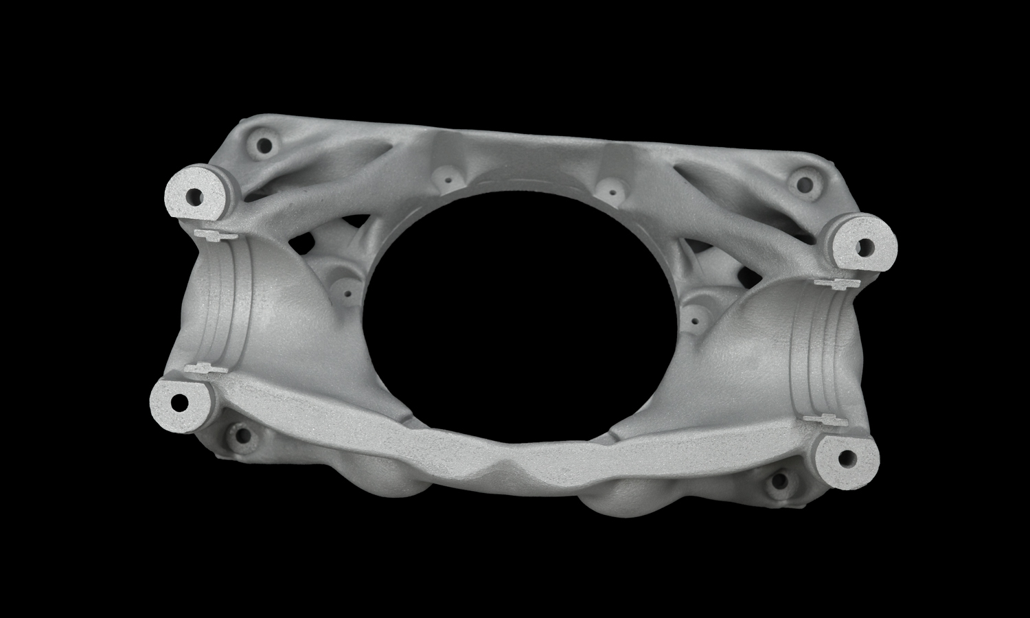
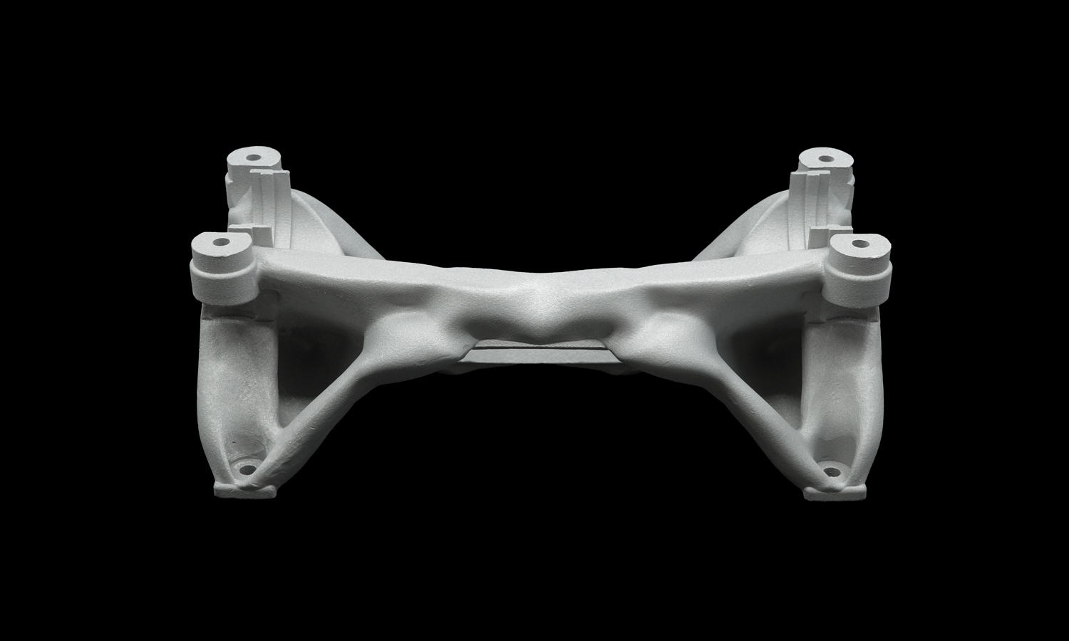
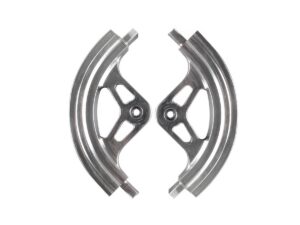
In the world of Formula SAE, every millisecond is earned through engineering excellence. For the University of Toronto Formula Racing team, the steering assembly isn’t just a mechanical linkŌĆöitŌĆÖs the driverŌĆÖs direct connection to the asphalt. We are thrilled to highlight the Rack Bottom Housing, a masterclass in balancing structural integrity with extreme weight optimization.
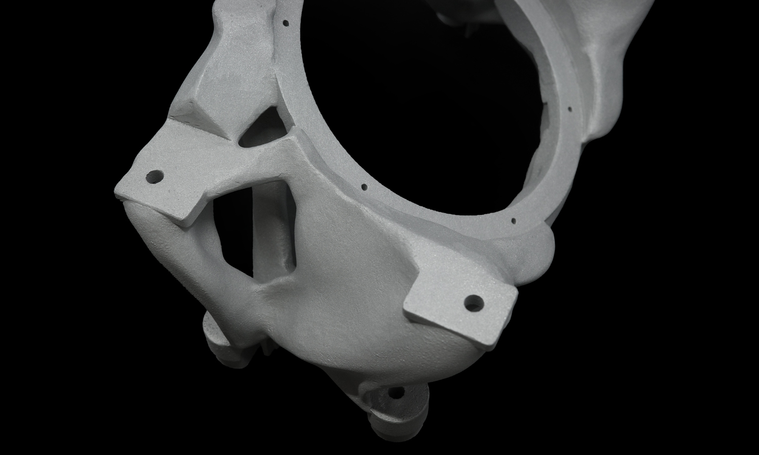
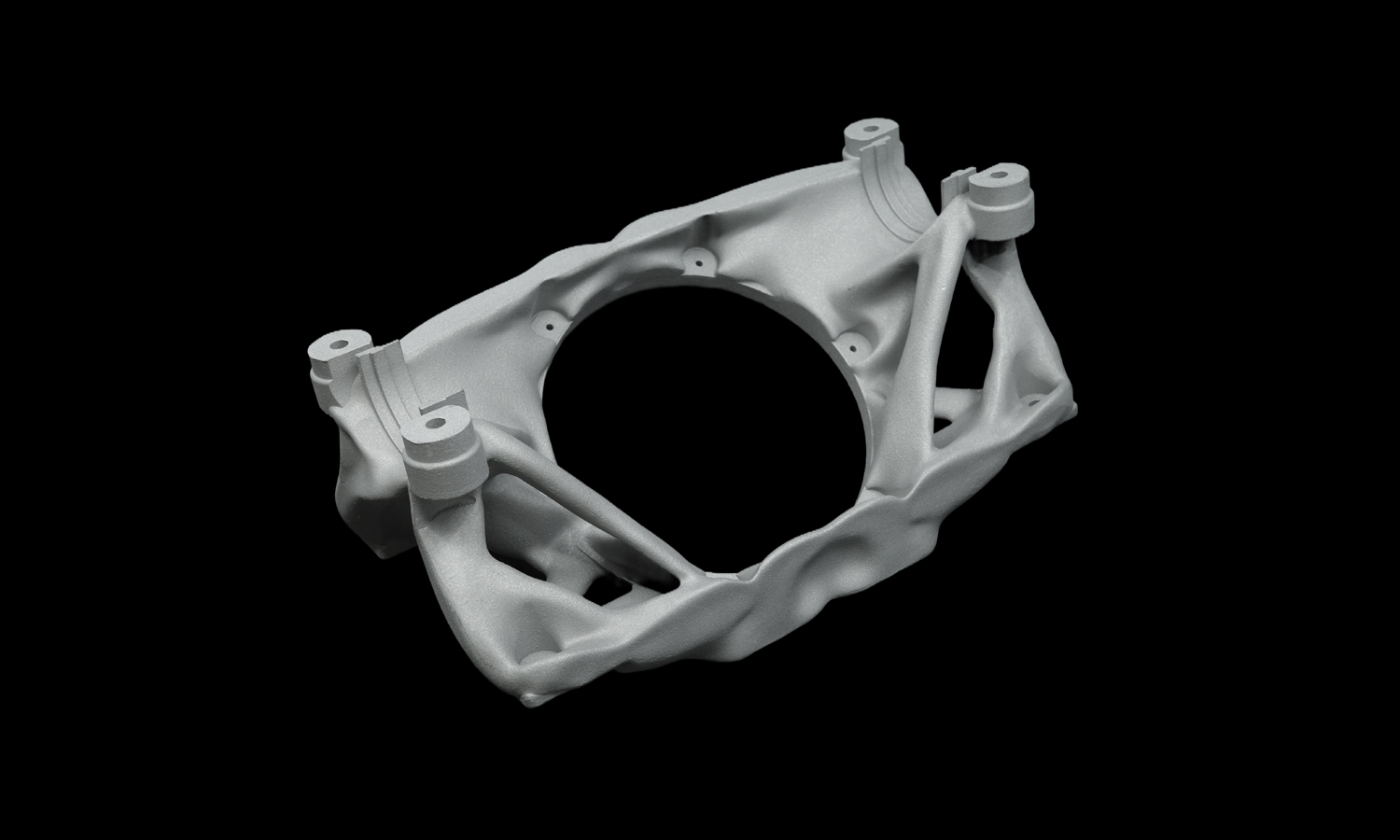
By moving away from traditional manufacturing, this component utilizes advanced internal geometries, such as the honeycomb lattice visible in the design. These structures provide the necessary stiffness to handle high-G cornering loads while drastically reducing the vehicle’s unsprung weight. In a sport where “ounces equal pounds,” this level of optimization is what puts teams on the podium. The design also incorporates critical post-machining surfaces, ensuring that while the body is lightweight and organic, the bearing fits and mating faces maintain aerospace-level tolerances.
Bringing these complex geometries to life requires more than just a standard 3D printer; it requires a deep understanding of metal additive physics. Whether itŌĆÖs the high-density results of DMLS and SLM, the speed and scalability of Binder Jetting, or the intricate precision of micro metal printing, these technologies are redefining what is possible in automotive design.
FacFox is proud to support the next generation of engineers by offering world-class metal 3D printing services. We specialize in the exact techniques used by elite racing teams, including DMLS, SLM, and Binder Jetting, providing the University of Toronto and other innovators with parts that are lighter, stronger, and more complex than ever before. If youŌĆÖre looking to shave seconds off your lap time or solve a complex structural challenge, partner with the experts who understand the rigors of high-performance engineering. Visit FacFox.com to explore our metal printing capabilities and get your project on the fast track today!
Solution
- Step 1: The optimized CAD geometry was converted into a sliced STL file, and support structures were strategically added to ensure stability during the thermal process.
- Step 2: A thin layer of high-strength aluminum alloy powder was uniformly spread across the build platform by a high-precision recoater blade.
- Step 3: A high-power fiber laser was utilized to selectively melt the powder, fusing the cross-section of the housing according to the digital blueprints.
- Step 4: The build platform was lowered by one-layer thickness, and the powder-spreading and laser-melting steps were repeated until the full height of the housing was achieved.
- Step 5: The completed part was carefully excavated from the powder bed, and the excess un-melted powder was recovered for future use.
- Step 6: Stress-relief heat treatment was performed on the component while it remained attached to the build plate to minimize internal residual stresses.
- Step 7: The housing was removed from the plate via wire EDM, and the support structures were manually detached using specialized hand tools.
- Step 8: Critical mating surfaces, including the rack bore and mounting faces, were post-machined to achieve the final required tolerances and surface finish.


