Material Metal, Porcelain
Quantity 1 pcs
Price Range $100-1,000
Lead Time 4 workdays
Gallery
About Project
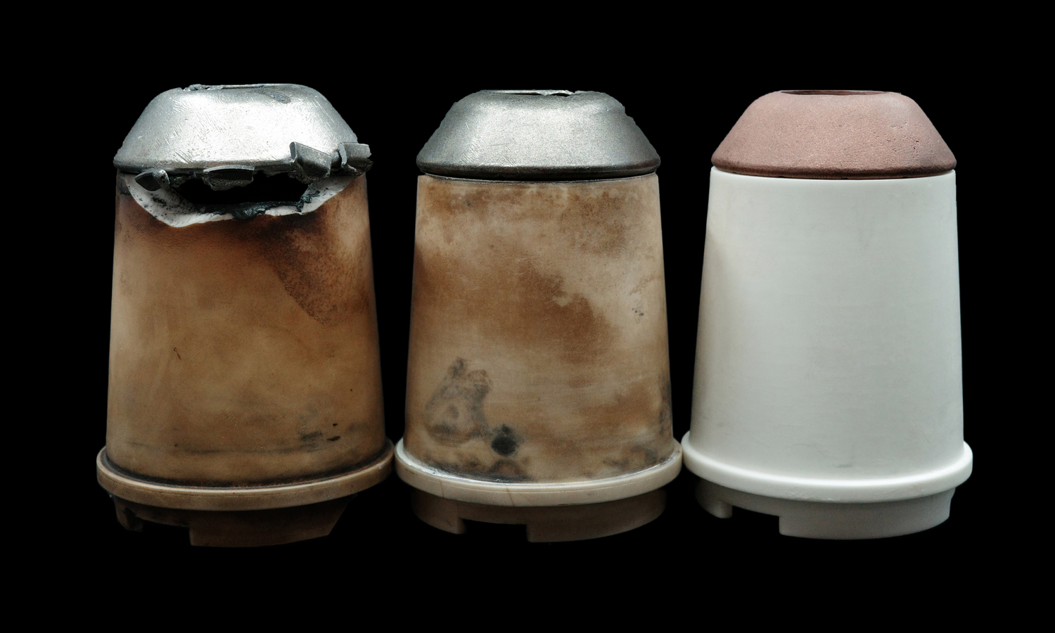
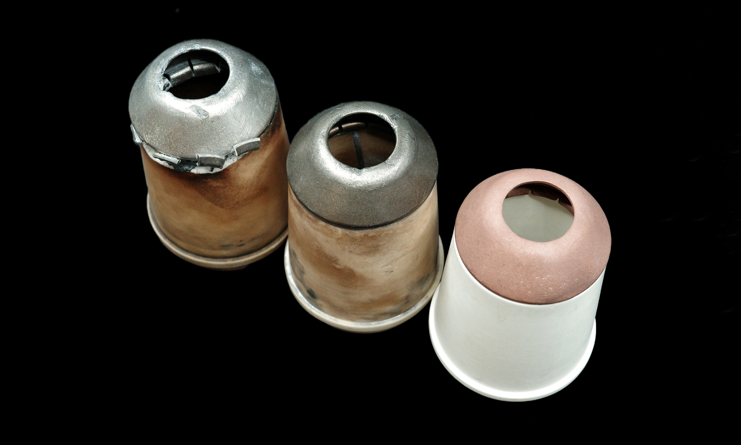
When a client brought us two severely worn plasma torch nozzles, the damage was evident. The metallic tops had eroded under extreme heat, while the ceramic bases were discolored and cracked from prolonged use. Instead of discarding the parts, we explored how advanced manufacturing could extend their life.
The Workflow
- 3D Scanning – The damaged nozzles were scanned with high precision, capturing every contour.
- Digital Reconstruction – Accurate 3D models of the original geometry were built, restoring worn surfaces to their intended design.
- Material Optimization – The nozzle was divided into two functional zones:
- Upper Part: Printed with Chromium Zirconium Copper (CuCrZr) for superior conductivity, heat resistance, and durability under plasma arc conditions.
- Lower Part: Printed with advanced ceramic material to provide thermal insulation and structural stability.
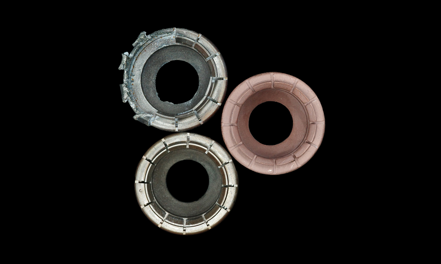
- Assembly Fit – The two parts were engineered to mate seamlessly. The upper copper alloy insert fits precisely into the ceramic base, ensuring both mechanical stability and reliable performance in high-temperature environments.
The Result
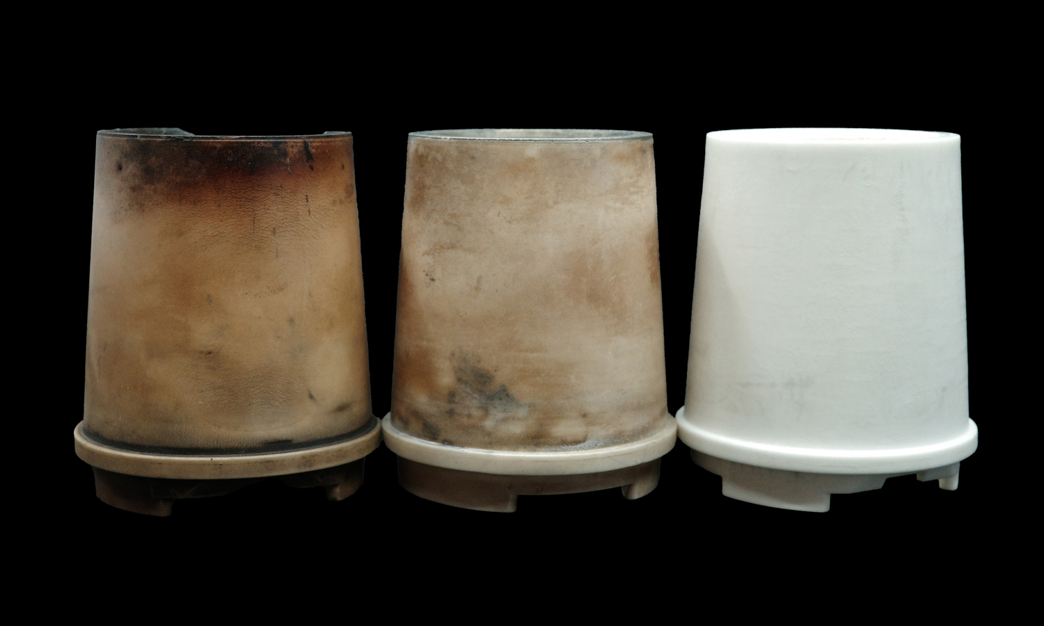
The restored nozzles now combine CuCrZr’s strength and conductivity with ceramic’s insulating properties, extending service life and reducing replacement costs. This hybrid approach not only revives worn components but also demonstrates how 3D scanning + multi-material 3D printing can solve real industrial challenges.
At FacFox, we specialize in bridging digital manufacturing with functional materials – from metals to ceramics – to deliver practical solutions for industries that demand performance under heat, stress, and time.
¤æē Whether it’s repairing, reverse engineering, or prototyping, FacFox is your partner in advanced 3D printing and hybrid manufacturing.
Solution
- Step 1: The worn nozzles were received, photographed, and tagged for traceability.
- Step 2: External residues were removed and reference targets were applied.
- Step 3: High-resolution scans were captured and point clouds were registered into a watertight mesh.
- Step 4: The original geometry was reconstructed; eroded areas were restored and datum features were defined.
- Step 5: The design was partitioned into two components: an upper conductive insert and a lower insulating body.
- Step 6: Fit tolerances and shrinkage/finishing allowances were added; the mating interface was engineered for a precise press/slip fit.
- Step 7: Build orientation and supports for the upper insert were planned to protect the orifice and sealing surfaces.
- Step 8: The upper insert was additively manufactured via metal powder-bed fusion using Chromium Zirconium Copper (CuCrZr) powder.
- Step 9: The metal part was removed from the build plate, support structures were taken off, and stress-relief heat treatment was performed.
- Step 10: Critical features of the metal insert were finish-machined and the orifice was reamed to tolerance.
- Step 11: The ceramic base was prepared with an orientation minimizing distortion and support marks.
- Step 12: The ceramic body was 3D printed via ceramic photopolymerization; the green part was cleaned, debound, and sintered with compensated shrinkage.
- Step 13: Functional faces on the ceramic were ground/lapped and the bore was honed to the target fit.
- Step 14: The CuCrZr insert was assembled into the ceramic body; concentricity and seating depth were verified.

