Gallery
About Project
If you are looking for a way to create high-quality metal parts with complex geometries and excellent mechanical properties, you might want to consider SLM 3D printing.
SLM stands for Direct Metal Laser Sintering, a process that uses a powerful laser to fuse metal powder layer by layer into solid objects. SLM 3D printing can produce parts with fine details, high accuracy, and good surface finish.
However, SLM 3D printing also has some limitations and challenges that you need to be aware of when designing your parts. One of them is the minimum wall thickness that can be printed successfully.
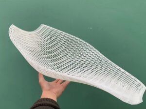
To help you understand this issue better, we have 3D printed some sample strips with SLM 3D printing technology and aluminum alloy powder. The sample strips are designed to show how the printing effect would vary with different thicknesses and what is a safe thickness for SLM 3D printing.
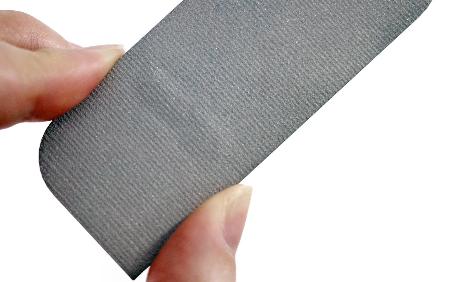
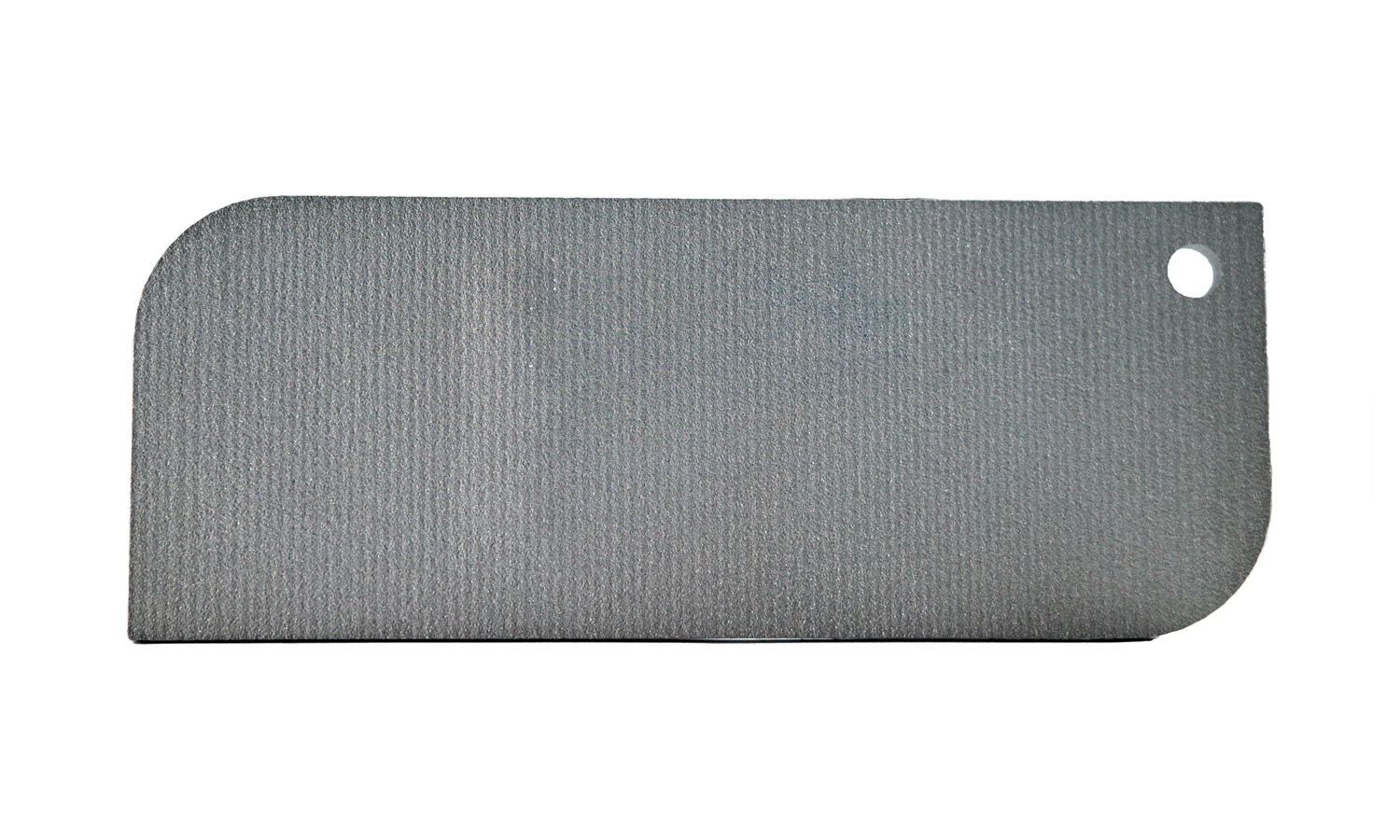
The sample strips also show how the raw finish looks like and what kind of surface finishing options are available for SLM 3D printed parts. As you can see from the pictures, the front and back faces of the sample strips have a roughness of Ra 3.2, which is typical for SLM 3D printing. You can also see how the laser moves and fuses the metal powder on the front face, creating a textured appearance. On the back face, there are uniform layer lines that indicate the direction of the laser scanning.
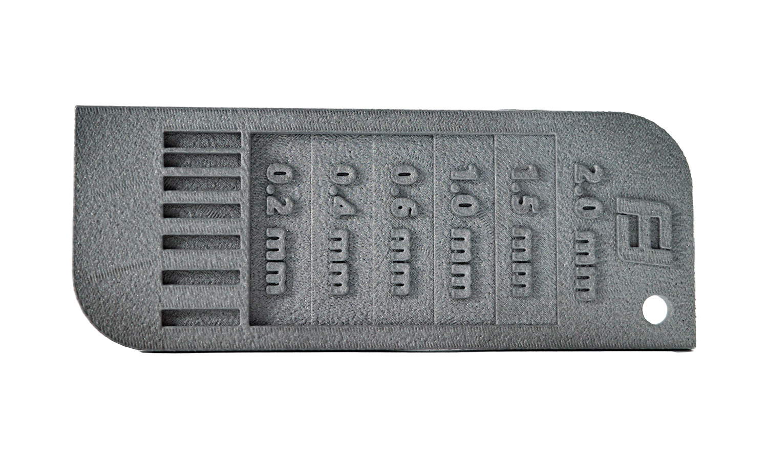
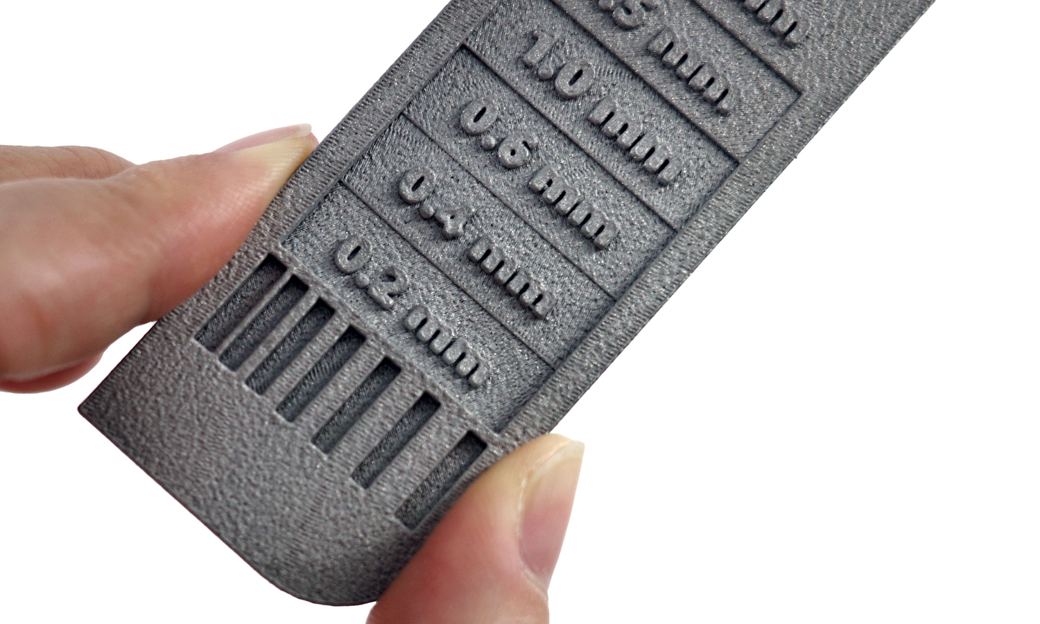
The sample strips have different thicknesses ranging from 0.2 mm to 1 mm. The 0.2 mm thick stage has already deformed and has a lump on the back, which means that it is too thin to be printed successfully. We recommend that you use a minimum wall thickness of 0.5 mm for SLM 3D printing, as thinner walls may not be able to withstand the thermal stresses and distortions that occur during the printing process.
Of course, the optimal wall thickness may vary depending on the geometry, orientation, and material of your part, so it is always advisable to consult with our experts before placing your order. At FacFox, we offer professional SLM 3D printing services with a wide range of metal materials, such as aluminum, titanium, stainless steel, inconel, and more.
We also offer various surface finishing options for SLM 3D printed parts, such as polishing, sandblasting, anodizing, coating, and more. You can choose the finish that best suits your needs and preferences, whether you want to improve the aesthetics, functionality, or durability of your part. FacFox is your one-stop shop for all your SLM 3D printing needs.
Visit our website today and get an instant quote for your project. You can also contact us at info@facfox.com if you have any questions or feedback about our services. We are always happy to help you create amazing metal parts with SLM 3D printing.
Solution
- Step 1: A 3D model was prepared and exported into a 3D printable file format (an STL format). The model was hollowed to reduce the amount of metal powder.
- Step 2: The file was loaded into the software and the printing parameters such as layer thickness, laser power and scanning speed were set up.
- Step 3: The build chamber was filled with Aluminum powder and leveled with a recoater blade.
- Step 4: The printing process started and the laser scanned each layer according to the file.
- Step 5: The part was allowed to cool down inside the build chamber before being removed.
- Step 6: Any support structures that were needed to prevent warping or distortion during printing were broken off.
- Step 7: Excess powder that remained on the part was cleaned off using brushes or compressed air.
- Step 8: The part was heat treated to improve mechanical properties and microstructure. No surface finishing is applied as we want to display the raw finish.
a 3D printable file format (an STL format). The model was hollowed to reduce the amount of metal powder, and the drain holes were set on each of Venus’ butt.

