- DMLS 3D Print Aluminum Sample with Ra 1.6 Hand Polish Finishing
- DMLS 3D Print Aluminum Sample with Ra 3.2 Raw Finishing
Gallery
About Project
We are excited to share with you a sample part we made using DMLS 3D printing technology. DMLS stands for Direct Metal Laser Sintering, which is a process that uses a laser to fuse metal powder layer by layer into solid parts. DMLS can create complex and precise metal parts that are difficult or impossible to fabricate with traditional methods.
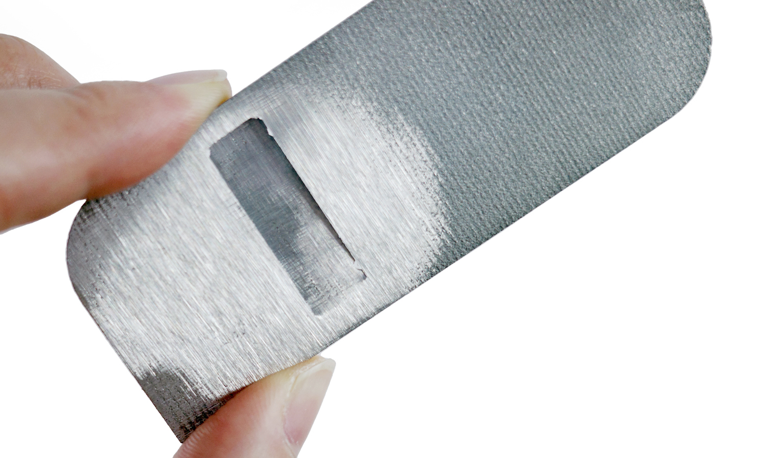
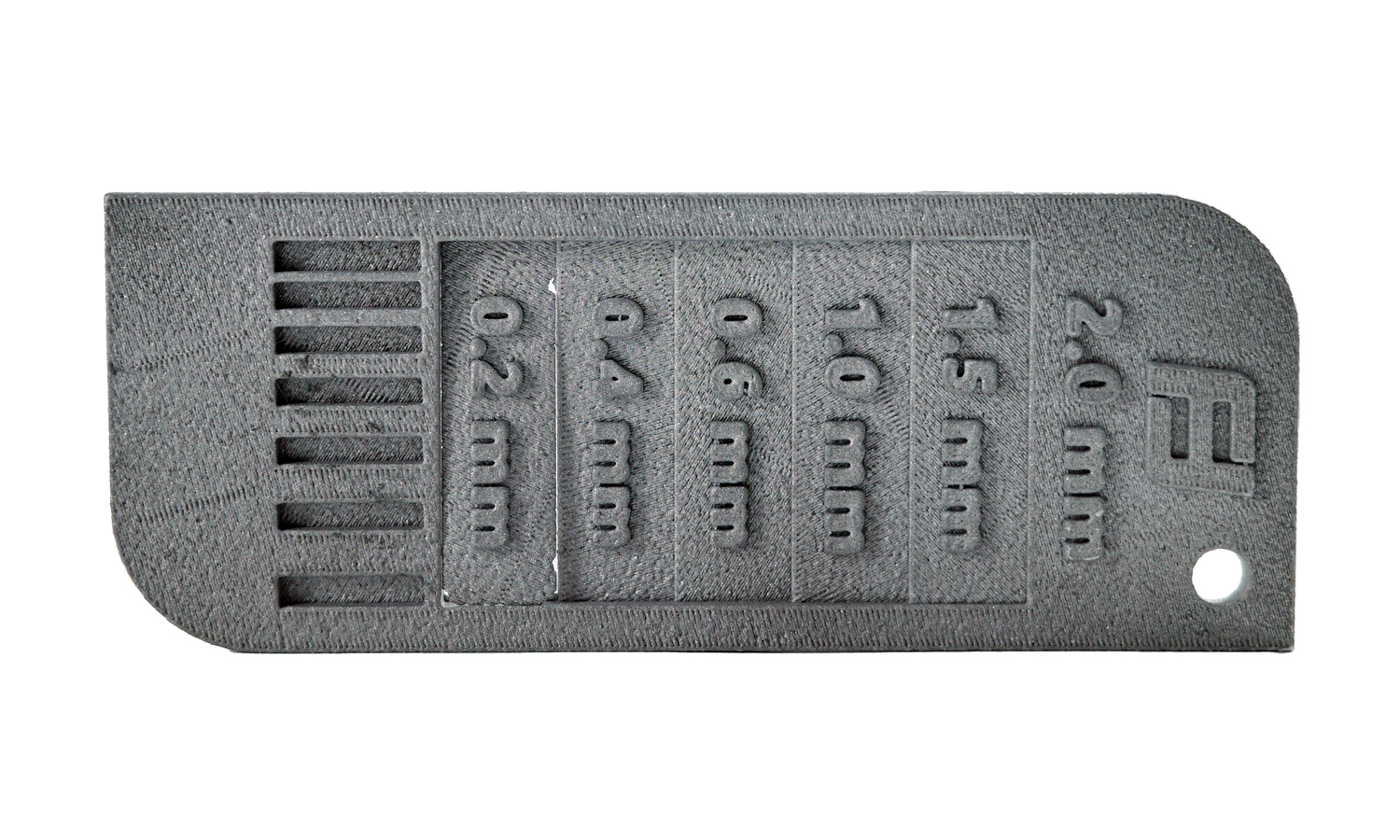
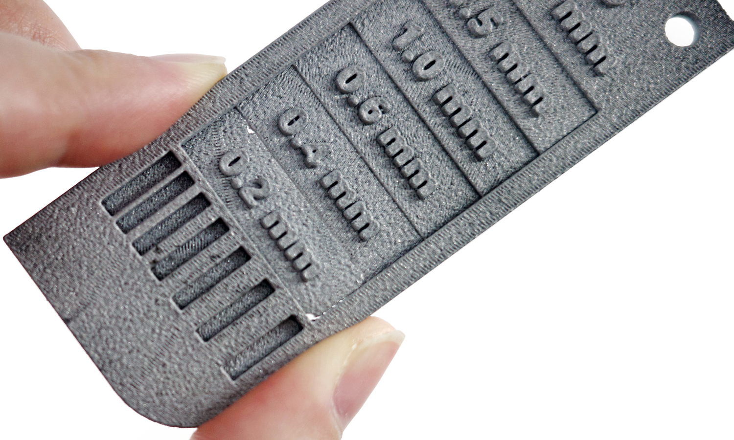
Our sample part is a strip of metal with stages of different thicknesses, ranging from 0.2mm to 2mm. The front face of the strip has a Ra 3.2 raw finish, which is the natural surface quality of DMLS parts. The back face of the strip has been partially brushed, which is a post-processing technique that can improve the surface smoothness and appearance of DMLS parts.
The brushing procedure involves using a rotary tool with a wire brush attachment to gently polish the surface of the part. The brush removes any loose powder or rough edges, and creates a uniform matte finish. The brushing can be done manually or automatically, depending on the size and shape of the part.
As you can see from the sample part, the brushing effect is more noticeable on thicker sections of the strip. The 0.2mm section of the strip has been broken, which shows that DMLS parts with very thin features may not be suitable for brushing. We recommend that your 3D models should have a minimum thickness of 1.2mm for the best brushing effect.
At FacFox, we offer DMLS 3D printing services for various metals and alloys, such as stainless steel, aluminum, titanium, copper, and more. We also offer various surface finishing services, such as brushing, sandblasting, polishing, anodizing, and coating.
Whether you need functional prototypes, custom parts, or small batches of metal products, we can help you achieve your goals with our high-quality DMLS 3D printing and post-processing solutions.
If you are interested in our DMLS 3D printing services or want to learn more about our capabilities, please visit our website facfox.com or contact us via info@facfox.com today. We would love to hear from you and help you with your next project!
Solution
- Step 1: A 3D model was prepared and exported into a 3D printable file format (an STL format). The model was hollowed to reduce the amount of metal powder.
- Step 2: The file was loaded into the software and the printing parameters such as layer thickness, laser power and scanning speed were set up.
- Step 3: The build chamber was filled with Aluminum powder and leveled with a recoater blade.
- Step 4: The printing process started and the laser scanned each layer according to the file.
- Step 5: The part was allowed to cool down inside the build chamber before being removed.
- Step 6: Any support structures that were needed to prevent warping or distortion during printing were broken off.
- Step 7: Excess powder that remained on the part was cleaned off using brushes or compressed air.
- Step 8: The part was heat treated to improve mechanical properties and microstructure. The metal surface was cleaned and sanded to prepare for brushing.
- Step 9: An abrasive brush and a polishing compound were used to create a pattern of unidirectional lines on the metal surface.

