Gallery


About Project
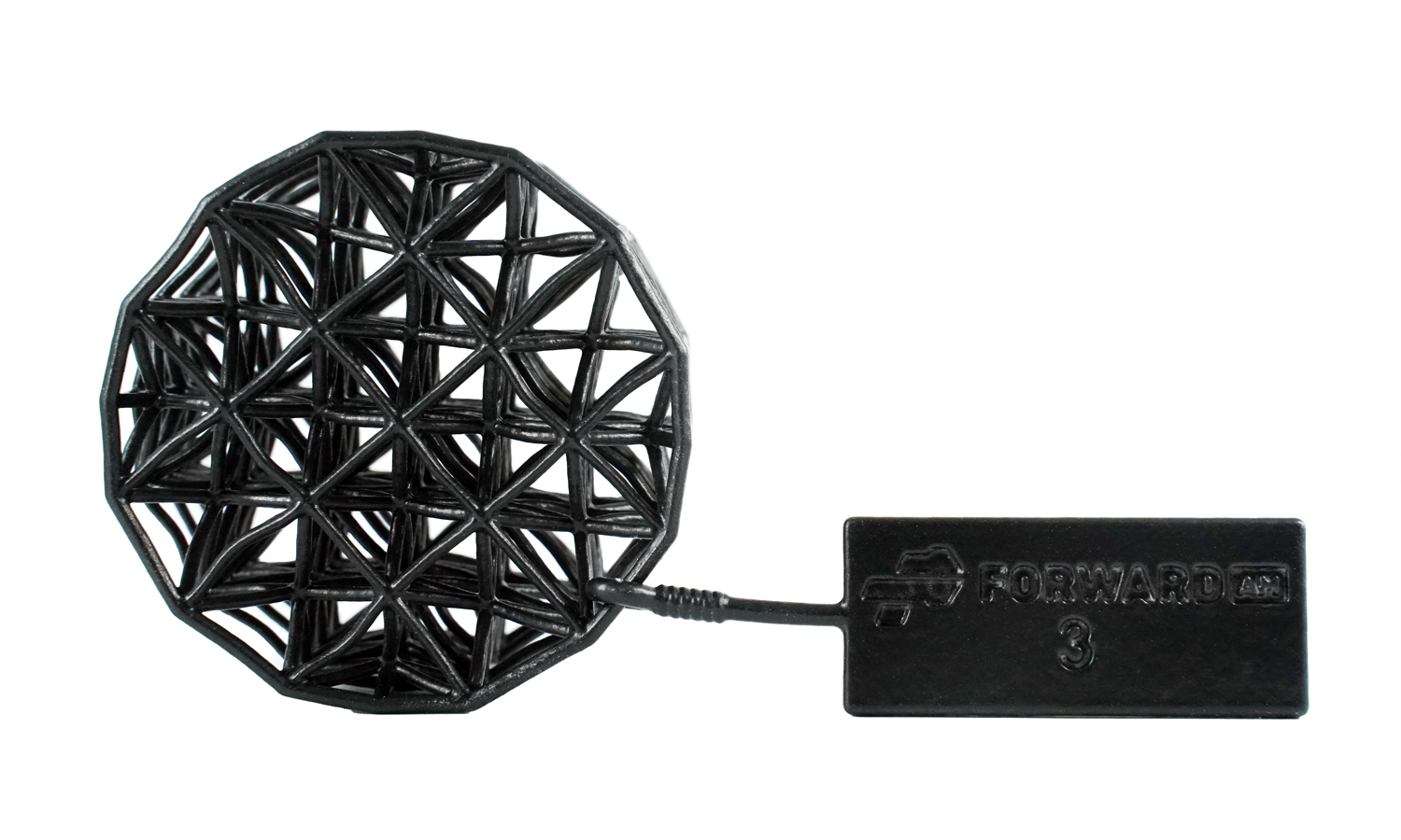
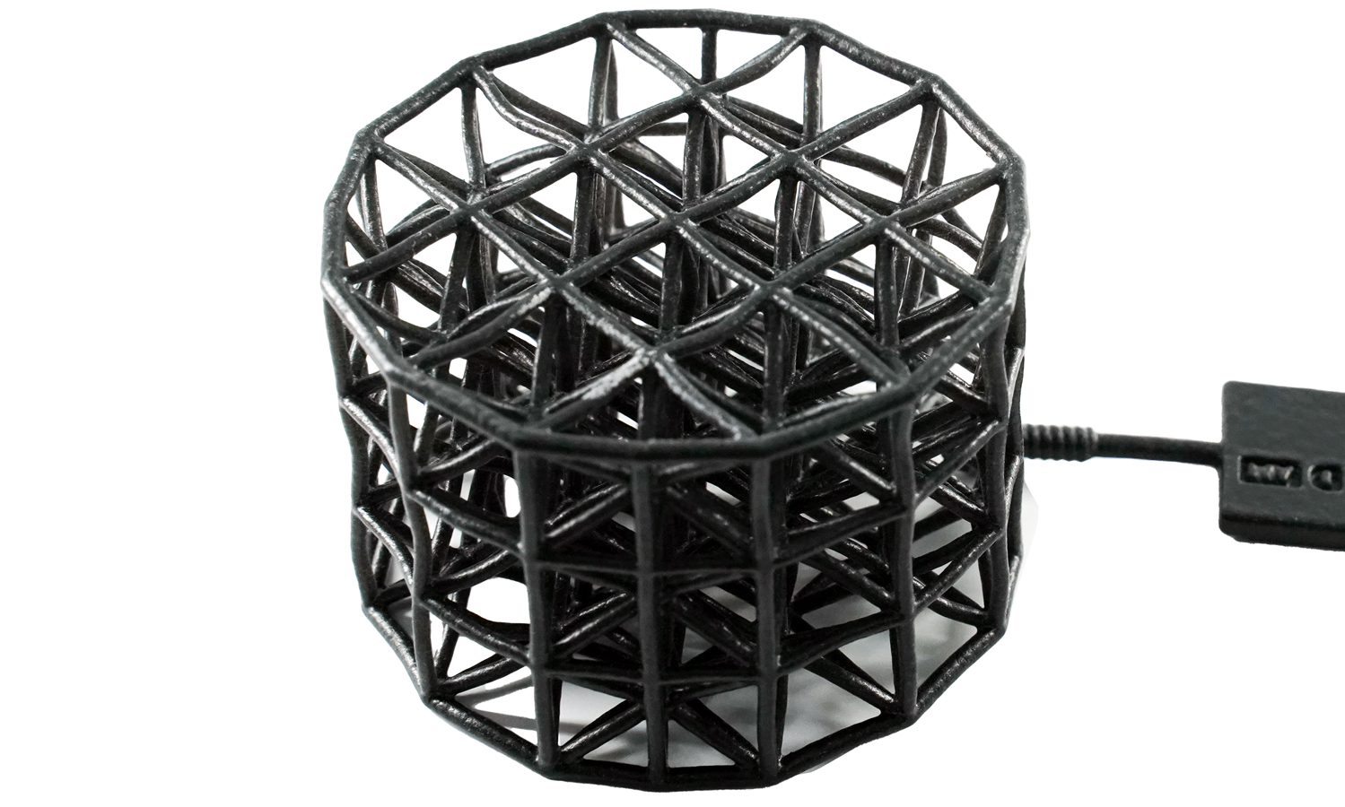
If you are looking for a way to create lightweight and flexible structures that can absorb shocks and vibrations, you should consider MJF 3D-printed TPU strut lattices.
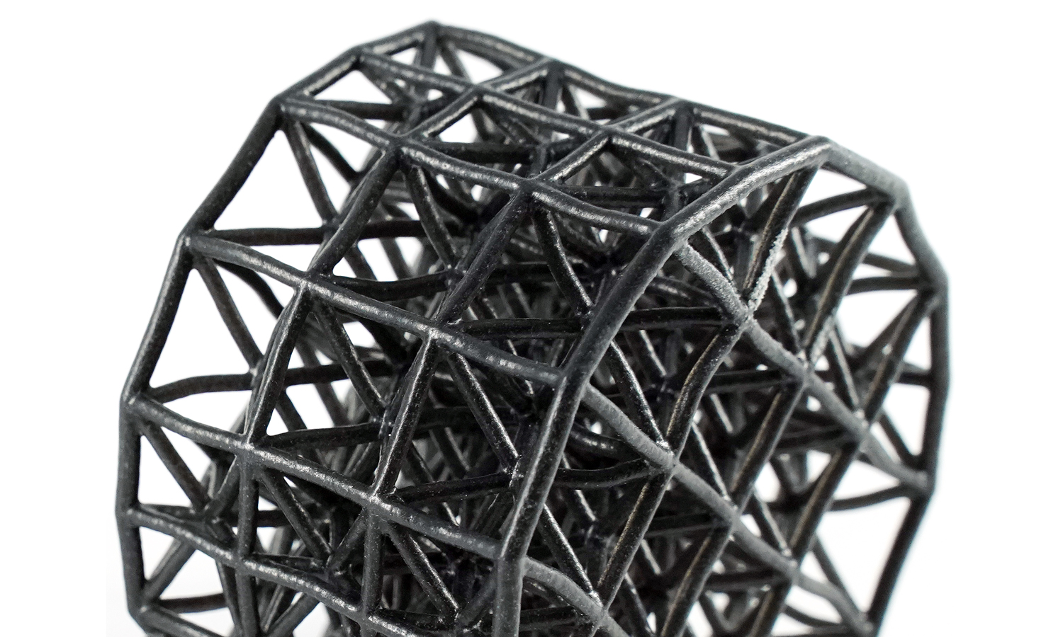
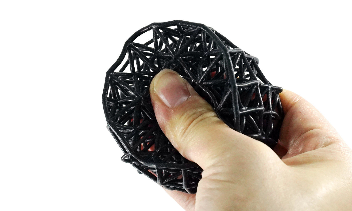
These are complex geometries that use TPU material to create thin and hollow beams that form a lattice pattern. TPU is a thermoplastic elastomer that has rubber-like properties, such as high flexibility, impact resistance, and wear resistance.
MJF 3D printing technology allows you to print TPU parts with high precision and resolution, as well as unlimited design possibilities. As a post-processing technique, vapor smoothing uses solvent vapor to smooth the surface of the part, enhancing its appearance and performance. Dyed black is a color option that gives the part a sleek and uniform look.
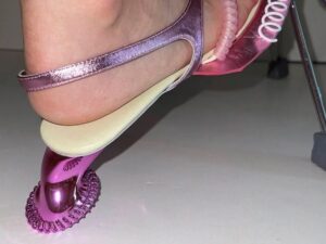
These TPU strut lattices can be used for various applications, such as aerospace, automotive, medical, robotics, and footwear. They can reduce weight, increase strength, improve airflow, and provide cushioning and damping effects. They can also be customized to fit different shapes and sizes.
If you want to get your own MJF 3D printed TPU pieces, you should visit FacFoxβÄôs website. FacFox is a professional online 3D printing platform that offers high-quality and affordable 3D printing services and post-processing services for TPU material. You can upload your 3D model, choose your material and finishing options, and get an instant quote. FacFox will print your part with their advanced MJF machines and ship it to you in a short time.
Solution
- Step 1: First, the 3D model would be broken down into layers of 0.1 mm on the computer and sent to the 3D printer.
- Step 2: Before printing, the tank was filled with MJF TPU Rubber powders. On a bed pressure, a 0.08 mm thick layer over the whole width was applied.
- Step 3: The material recoater carriage moved across the build area, depositing a thin layer of the powder material. The printing and fusing carriage moved across the build area, preheating the powder to a specific temperature to provide material consistency.
- Step 4: An array of inkjet nozzles fused agents onto the powder bed in areas that correspond to the partβÄôs geometry and properties. After each layer was finished, the build unit retracted to create space for the next layer of material to be deposited.
- Step 5: This process repeated until the build was completed. When the printing process ended, the excess powders were removed which also served as supports.
- Step 6: The print was cleaned and placed in a vapor smoothing chamber that contains a solvent vapor. It was then soaked in a dye bath for minutes and dried.


