SLS Black Nylon Gear Shift Trim Bezel for a Jeep Renegade

SLS Black Nylon Gear Shift Trim Bezel for a Jeep Renegade

facfox-case-study
Process 3D Print
Material Plastic
Quantity 1 pcs
Price Range $1-100
Lead Time 14 workdays

Gallery

About Project

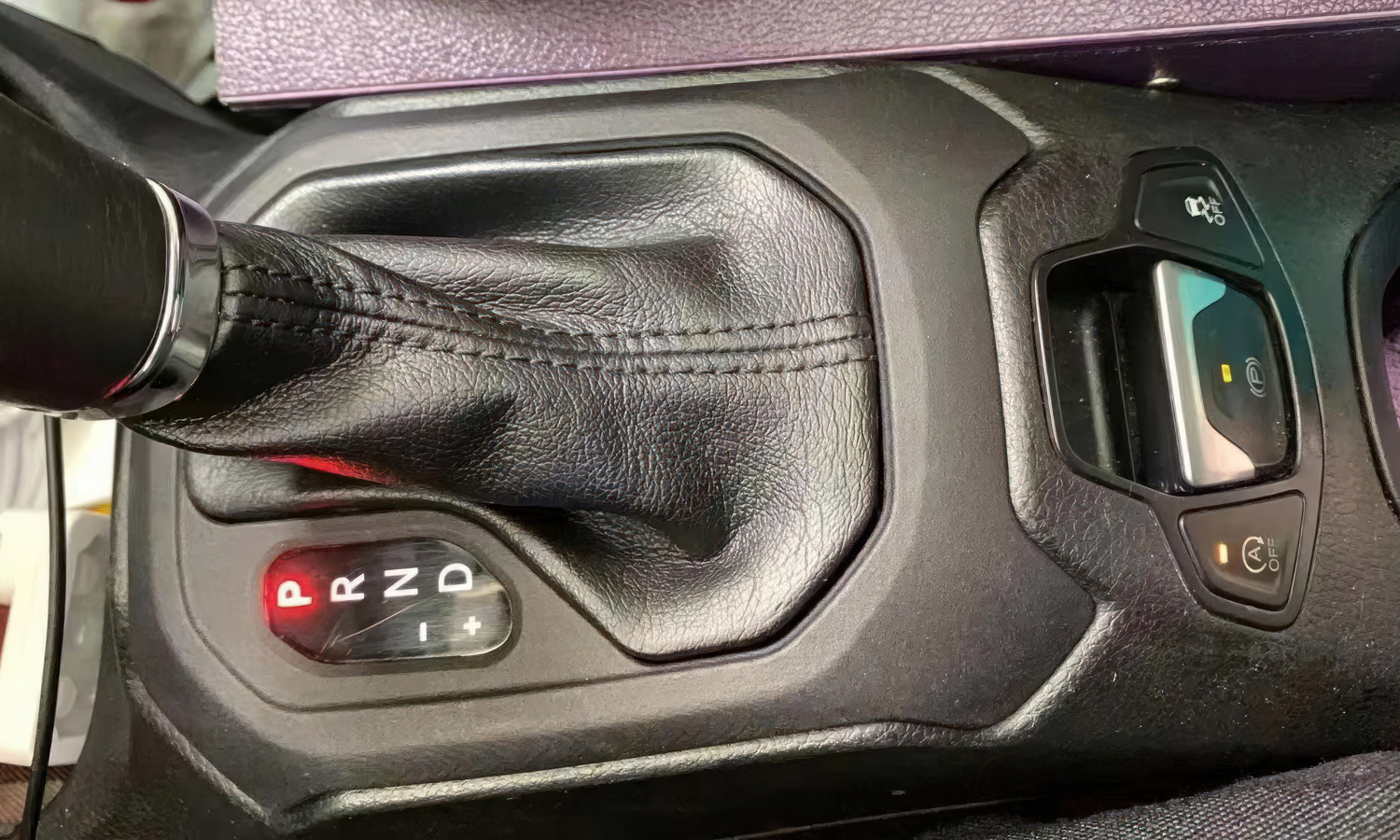
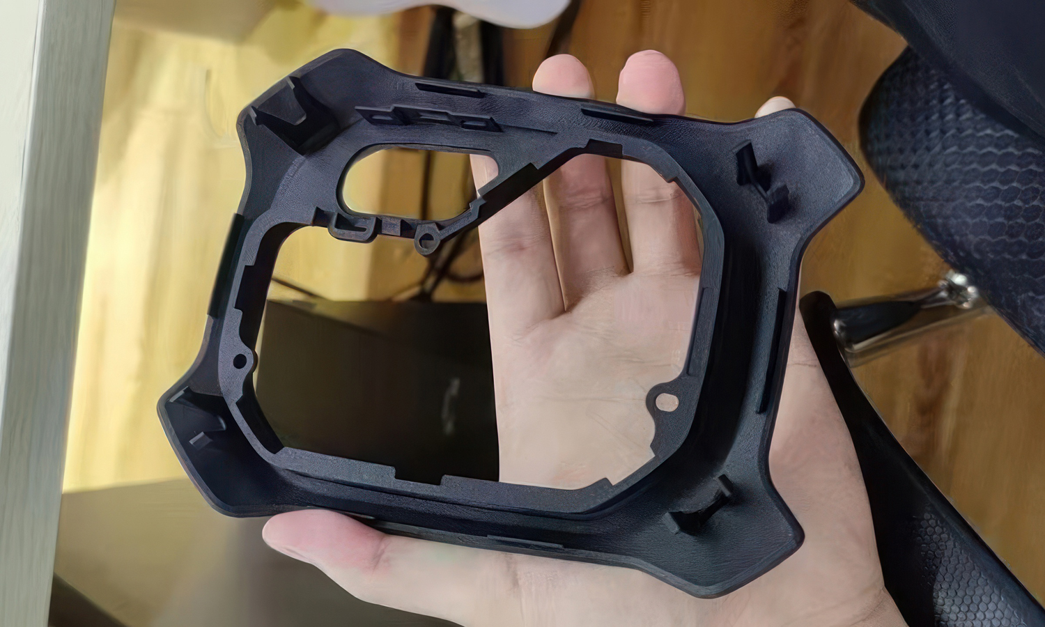
This custom gear shift trim bezel was developed for the center console of a Jeep Renegade. The large central opening surrounds the shifter boot, while the narrow opening beside it frames the illuminated gear-position display.

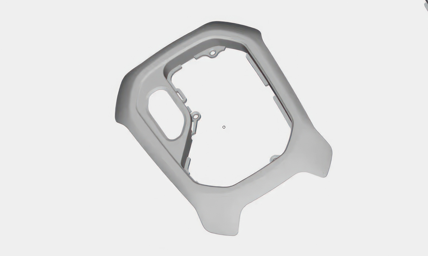
The project used 3D scan data to reconstruct the bezel in CAD, then turned the digital model into an SLS black nylon prototype for an in-vehicle trial fit. The prototype reproduces the visible contour as well as the clips and mounting holes on the underside. Fitting it on the console lets the team assess the perimeter gap and the alignment of both openings in their installed positions.

For custom interior trim projects, FacFox can help reconstruct parts from scan data and produce prototypes for checking clips, mounting points, and visible gaps on the vehicle. Share your scan files, CAD model, or reference photos to discuss the project. FacFox website · info@facfox.com

Challenge

The bezel fits between the center console, the shifter boot, and the gear-position display. Its visible perimeter must follow the console contours while the underside clips and mounting holes line up with their mating features. A shift in the position of either opening can affect the fit around the boot or the alignment of the display.
Solution

  • Step 1: Review the reference trim and console interfaces. Identify the visible perimeter, shifter boot opening, indicator window, and mounting points to capture.
  • Step 2: Capture the reference geometry with 3D scanning. Use the scan as a basis for reconstructing the trim surfaces and key mounting features in CAD.
  • Step 3: Check the reconstructed opening profiles, mounting holes, and clip locations against the reference. Review the build orientation to balance the flatness of the thin perimeter frame with the accuracy of the clips and openings.
  • Step 4: Slice the model and print it in black nylon using selective laser sintering (SLS). The laser fuses the cross-section of each layer, while the surrounding unfused powder supports the frame and underside features during the build.
  • Step 5: Let the powder bed cool before removing the bezel. Brush away loose powder and use controlled air cleaning as needed around the clip roots, mounting holes, and recessed edges.
  • Step 6: Inspect the cleaned bezel for warpage, damaged clips, and remaining powder. Lightly dress any rough spots that could interfere with seating, preserving the clip geometry and opening dimensions.
  • Step 7: Trial-fit the bezel on the vehicle. Check the perimeter gap and flushness, gear-position display alignment, clip engagement, and shifter boot clearance throughout lever travel.
  • Step 8: Use the trial-fit observations to identify any CAD adjustments needed before the next prototype.