FDM 3D Printed Tracked Stacker Concept Model

FDM 3D Printed Tracked Stacker Concept Model

facfox-case-study
Process 3D Print
Material Plastic
Quantity 1 pcs
Price Range $1-100
Lead Time 3 workdays

Gallery

About Project

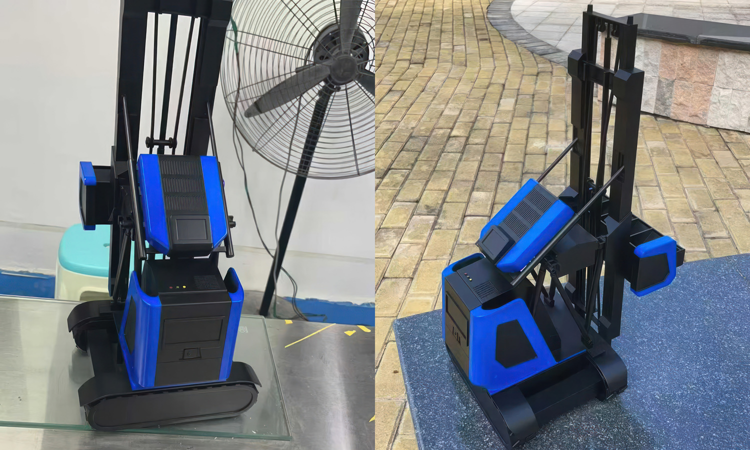
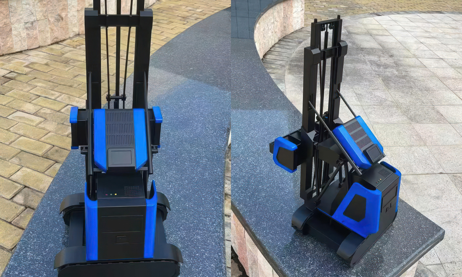
This concept model represents a tracked stacker with a tall lifting mast, crawler chassis, rear counterweight body, and integrated control and sensor details. The tracked layout suggests use on uneven terrain, outdoor yards, construction sites, or other low-ground-pressure applications, while the angular blue-and-black body gives the machine a modern robotic identity.

FDM was selected for its practical balance of size, cost, speed, and modular production. Large housings and structural parts could be printed as lightweight sections, while smaller details could be produced separately for easier assembly or revision. The finished model is suitable for design review, exhibition, and concept communication. Contact FacFox or upload your 3D files for a quote.
Solution

  • Step 1: Recommend a suitable process and material based on the client’s requirements and budget, assess printing and assembly risks, and discuss necessary model revisions with the client.
  • Step 2: Prepare the model for FDM by separating the mast, chassis, body covers, tracks, rods, control components, and other details into practical printing and assembly modules.
  • Step 3: Adjust thin features, add locating structures, and define clearances so the long guide elements remain printable and the modules can be aligned without excessive gaps.
  • Step 4: Select build orientations and support strategies for the tall mast, long rods, flat covers, and curved track parts, balancing strength, straightness, surface quality, and support removal.
  • Step 5: Set wall thickness, perimeter count, infill, layer height, temperature, and speed according to each part’s size and function, then print the components while monitoring warping and layer bonding.
  • Step 6: Remove supports, trim and sand the contact points, clear narrow slots, and dry-fit the assemblies to check mast alignment, track symmetry, interface fit, and overall stability.
  • Step 7: Bond the main modules and reinforce critical joints where required, installing the rods, pulley details, cables, control boxes, and other smaller parts in sequence.
  • Step 8: Fill and sand visible seams, apply primer, create the blue-and-black color separation with masking and spray finishing, and hand paint the screens, indicators, and sensor details.
  • Step 9: Complete final assembly and touch-ups, then inspect the straightness of the mast, the balance of the chassis, the visual alignment of moving-system details, and the consistency of the finished surfaces.