Gallery
About Project
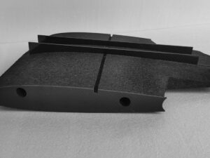
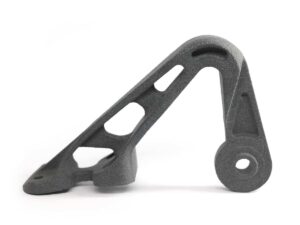
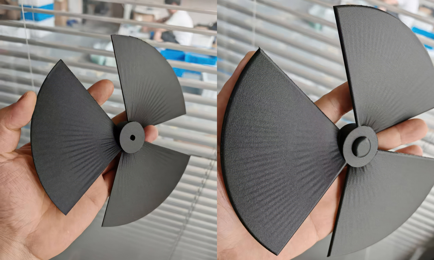
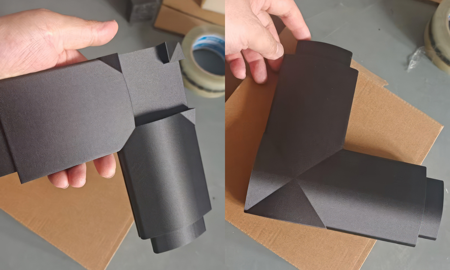
Based on their geometry, the round component is most likely a four-blade propeller or axial impeller prototype. The other two parts appear to be curved airflow guides, duct transitions, or protective housings with integrated connection features. Together, they demonstrate how FDM can produce lightweight functional parts with broad aerodynamic surfaces, compact hubs, angular transitions, and integrated interfaces.
All of the parts were produced by FDM 3D printing in carbon-fiber-filled PETG, commonly called PETG-CF. This material combines a PETG thermoplastic matrix with chopped carbon fibers. Compared with standard PETG, the fiber-filled formulation is generally stiffer and more dimensionally stable, with reduced shrinkage and a fine matte texture that helps soften the appearance of layer lines. Those characteristics make it useful for functional prototypes, fixtures, housings, ducts, brackets, and low-volume mechanical parts that need more rigidity than ordinary PETG can provide.
PETG-CF should not be confused with a continuous carbon-fiber laminate. The short fibers improve stiffness and print behavior, but the printed part remains anisotropic and its strength still depends on build orientation, wall design, infill, and layer bonding. The fibers are also abrasive, so production normally requires a wear-resistant nozzle, controlled material drying, and carefully tuned extrusion settings. In this project, the material delivered lightweight parts with stable broad surfaces, crisp silhouettes, and a consistent dark technical finish directly from the printer. Contact FacFox or upload your 3D files for a quote.