Material Resin
Quantity 1 pcs
Price Range $1-100
Lead Time 3 workdays
Gallery
About Project
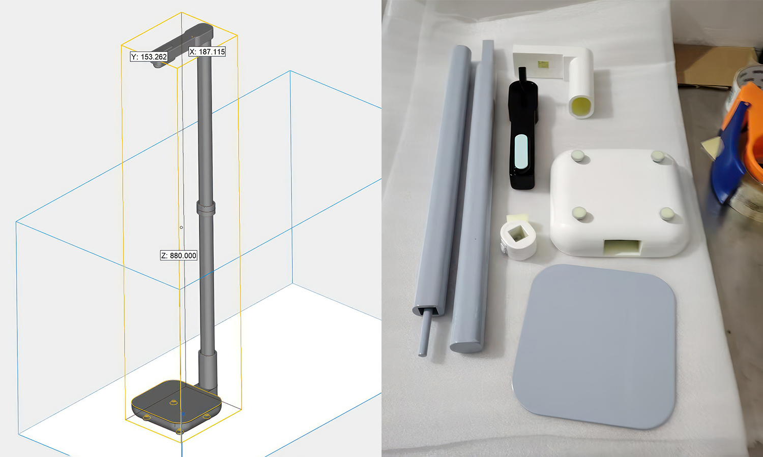
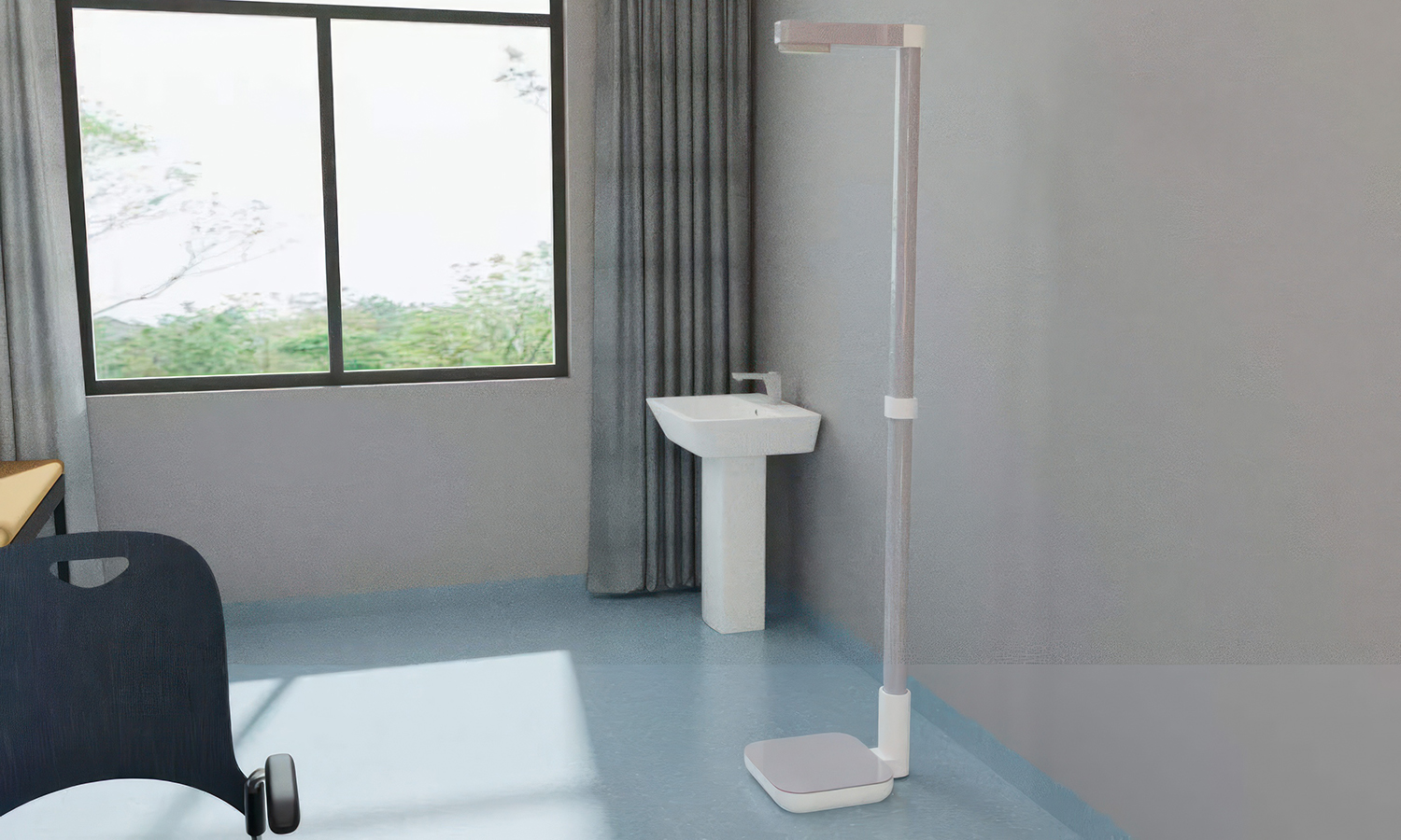
In a market captivated by towering, overhead floor lamps for study spaces, industrial designers face a unique challenge: how do you cost-effectively prototype a massive, nearly meter-tall home appliance without breaking the bank or dealing with shipping nightmares? This sleek, road-lamp-inspired study light offers a masterclass in clever, practical design simplification for visual verification.
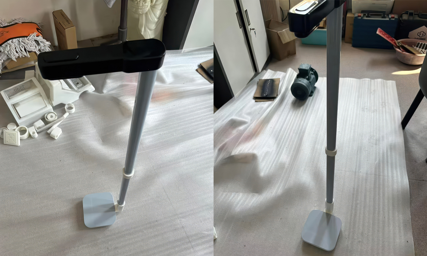
Instead of overcomplicating the prototype with dual-sided lighting or complex internal gas springs, the designer stripped this model down to its pure aesthetic essentials. It features a downward-directed cantilevered arm, a heavy-set rounded rectangular base, and a statuesque vertical stance. To overcome the size limitations of standard 3D printers and prevent structural warping during transit, the $880\text{ mm}$ upright pillar is smartly split into two identical, semi-oval shafts. A single white interlocking ring acts as the central structural coupling, snapping the segments together seamlessly while introducing a clean, color-blocked accent that breaks up the long grey profile.
A closer look at the disassembled components reveals just how production-thoughtful this appearance model is. The back of the shaft features a dedicated cable routing channel to conceal wiring, and the bottom housing is outfitted with non-slip feet. While its height remains fixed and its light strictly direct, the meticulous partitioning and material separation allow this static prototype to achieve an incredibly high-fidelity, shelf-ready look.
When it comes to bringing slender, large-scale hardware concepts to life with zero margin for error, FacFox’s SLA 3D printing services are the ultimate designer’s toolkit. Long, thin structural components are notoriously prone to warping, but FacFox utilizes industrial-grade SLA technology and high-toughness resins to guarantee microscopic tolerance control, ensuring every split joint fits flawlessly. Combined with FacFox’s premium post-processingŌĆöincluding flawless matte-and-gloss paint finishes and meticulous hand-sandingŌĆöyour initial concepts will emerge looking identical to mass-produced injection-molded retail units. Turn your next big furniture or hardware breakthrough into a physical masterpiece with FacFox.
Solution
- Step 1: Digital Model Design and Slicing. The 3D CAD data of the lamp partsŌĆöcomprising the base cover, the hollŃĆéow bottom housing, two identical semi-oval shafts, the central interlocking ring, the L-shaped connector, and the horizontal light armŌĆöwas prepared and verified for a total bounding box height of $880\text{ mm}$. The digital assembly was then digitally sliced into thin horizontal layers to generate the toolpaths for construction.
-
Step 2: SLA 3D Printing. Industrial-grade Stereolithography (SLA) technology was utilized to execute the fabrication process. High-toughness liquid photosynthetic resin was layered and selectively cured by an ultraviolet laser beam within the printer bed, liquidifying and solidifying the intricate geometries of the components while strictly controlling tolerances for the split joints.
-
Step 3: Support Removal and Cleaning. Once the printing cycle was completed, the green-state components were removed from the build platform. The temporary sacrificial support structures required for the cantilevered light arm and hollow connector channels were carefully detached, and all parts were thoroughly washed in an isopropyl alcohol (IPA) bath to eliminate any residual uncured resin.
-
Step 4: UV Post-Curing. To achieve full cross-linking, maximum structural rigidity, and material stability, all washed resin components were placed into a specialized UV curing chamber. The parts were exposed to high-intensity ultraviolet light for a designated period to completely finalize the polymerization process.
-
Step 5: Surface Post-Processing and Hand-Sanding. The cured parts were subjected to a rigorous post-processing regimen to erase all visible layer lines and support scars. The exterior faces of the components were meticulously hand-sanded with progressive grits of sandpaper until a perfectly uniform, smooth finish was achieved across all curved and flat sections.
-
Step 6: Primer and CMF Painting. A high-quality primer coat was applied to seal the surfaces and ensure optimal paint adhesion. Following the primer application, the components were painted according to the designated CMF (Color, Material, Finish) specifications: the horizontal light head was finished in a glossy/matte black paint, the two vertical shaft segments and top base plate were coated in a light matte grey, and the modular connecting joints were sprayed with a solid white finish.
-
Step 7: Component Assembly. After the paint coats were fully dried, the final physical assembly was performed. The two identical grey poles were coupled together using the white interlocking center ring, an internal power cable was routed through the integrated wire guide channel on the back of the shafts, the L-shaped connector and black light head were mounted to the top, and the entire upright structure was anchored into the white bottom housing, which was completed by affixing four non-slip rubber feet to the underside.


