Gallery
About Project
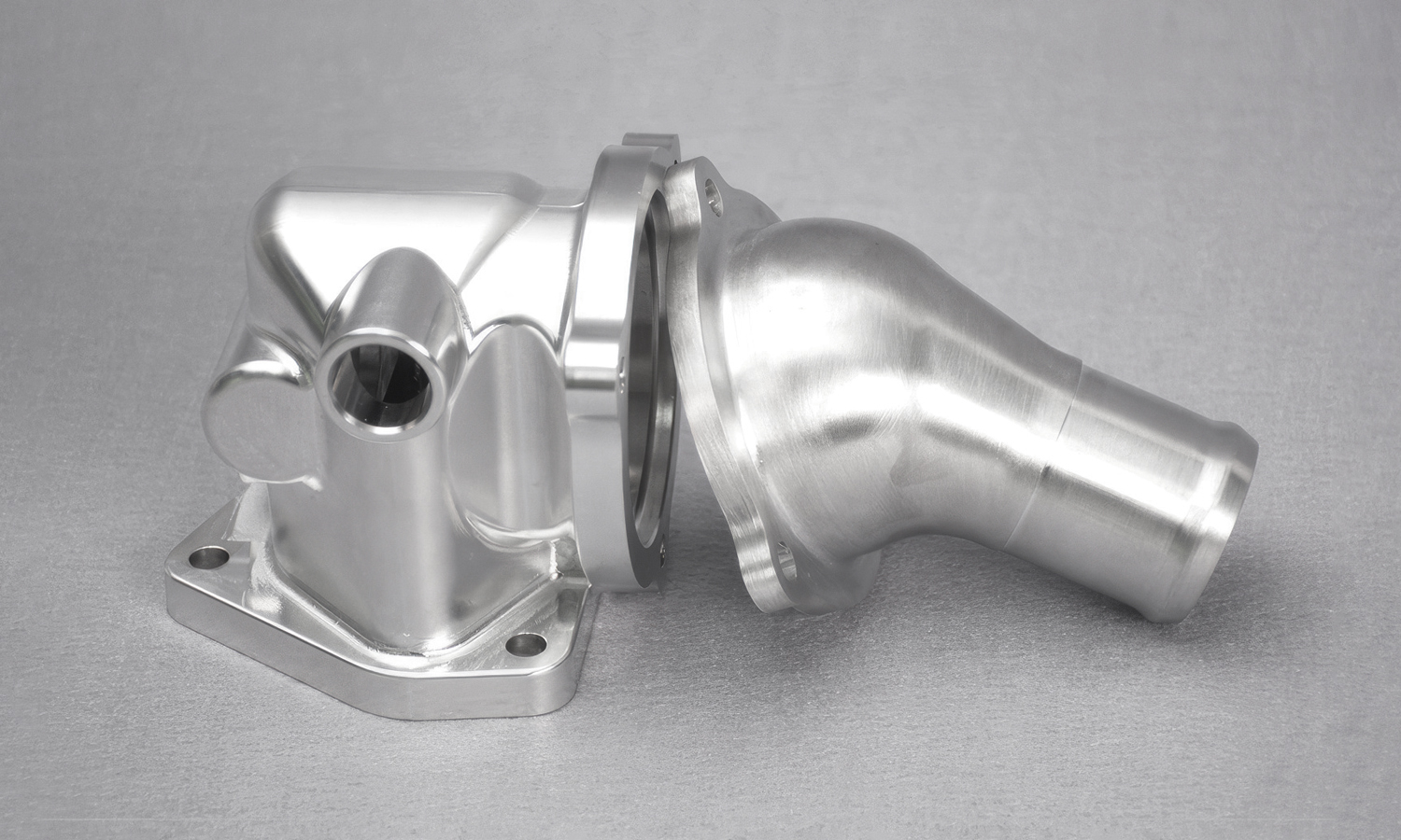
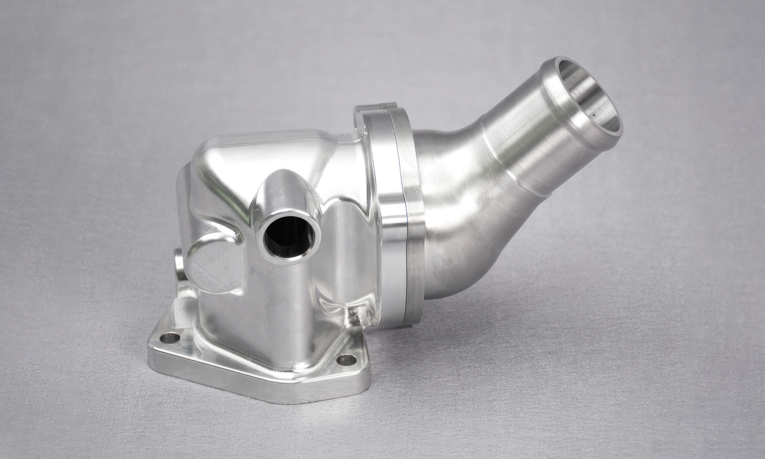
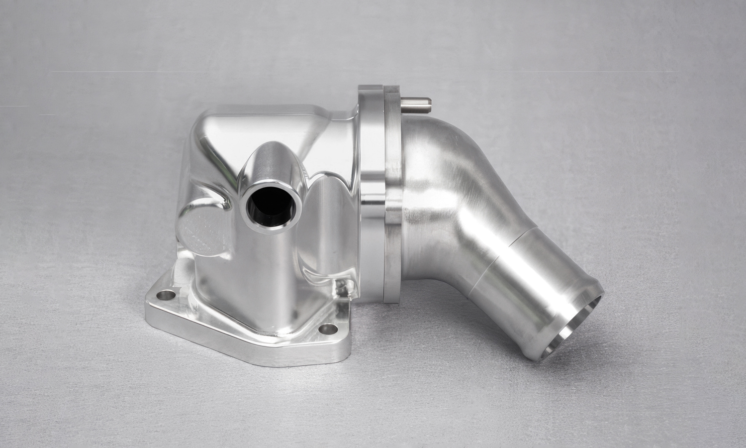
This CNC machined aluminum alloy coolant outlet assembly showcases the precision and functionality required in high-performance automotive cooling systems. Comprising two interlocking parts-a robust housing and a smoothly curved outlet pipe-this component is engineered to manage coolant flow efficiently between the engine block and external radiator systems.
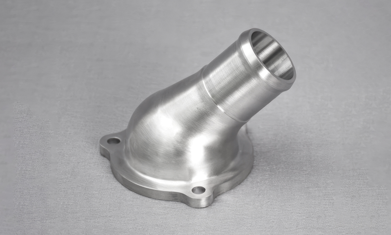
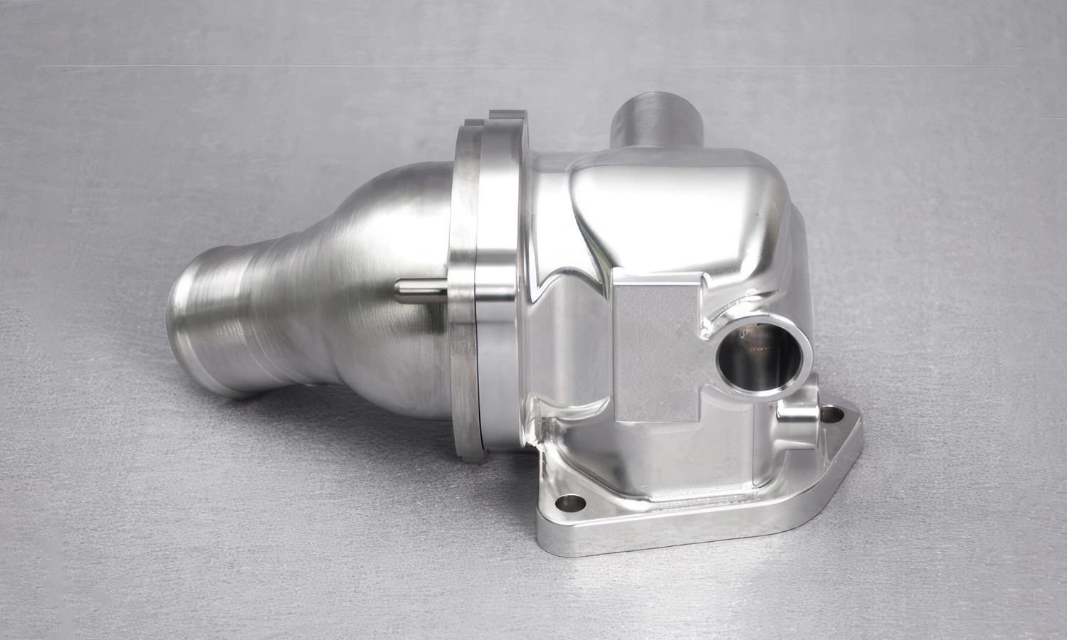
The housing features a flanged base with bolt holes for secure attachment to the engine block or thermostat housing. It includes a precision-machined internal bore designed for accurate alignment and optimal fluid sealing. The curved outlet pipe, also flanged, mates seamlessly with the housing, forming a fluid-tight junction. The flared geometry of the pipe ensures smooth, laminar coolant flow, minimizing turbulence and enhancing thermal efficiency.
Crafted from corrosion-resistant aluminum alloy, the entire assembly benefits from excellent thermal conductivity, strength-to-weight ratio, and long-term durability. The fine surface finish-achieved through advanced CNC milling and turning-reflects the tight tolerances and complex geometries that only precision machining can deliver.
This kind of coolant outlet assembly is vital in regulating engine temperature and ensuring long engine life, especially in performance vehicles where heat management is critical.
FacFox provides industry-leading CNC machining services tailored to the automotive sector. With expertise in aluminum alloy components and tight-tolerance assemblies, we help manufacturers bring complex designs to life with speed, accuracy, and repeatability. Whether you’re prototyping or producing at scale, trust FacFox to deliver precision-engineered parts that meet the rigorous demands of the modern automotive industry.
Solution
- Step 1: The aluminum alloy billet was selected and cut to rough dimensions using a bandsaw.
- Step 2: The billet was secured on a CNC milling machine for rough machining of the housing and pipe shapes.
- Step 3: Critical surfaces and flanges were precision-milled to achieve flatness and dimensional accuracy.
- Step 4: Internal bores and fluid passages were CNC drilled and reamed to exact tolerances.
- Step 5: The flanges were machined with bolt hole patterns using high-precision positioning.
- Step 6: The curved outlet pipe was turned and milled using a multi-axis CNC lathe to achieve smooth transitions and consistent wall thickness.
- Step 7: Both components were deburred, cleaned, and bead-blasted or polished for a uniform surface finish.
- Step 8: Final inspection was performed using coordinate measuring machines (CMM) to verify dimensions and alignment.


