Material Metal
Quantity 1 pcs
Price Range $100-1,000
Lead Time 3 workdays
Gallery
About Project
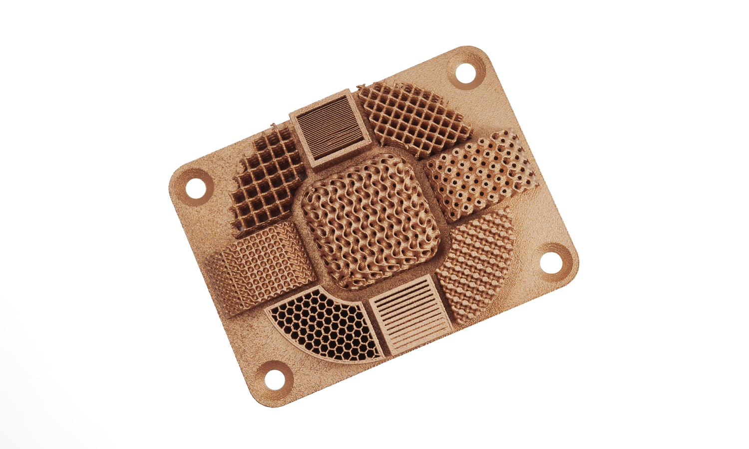
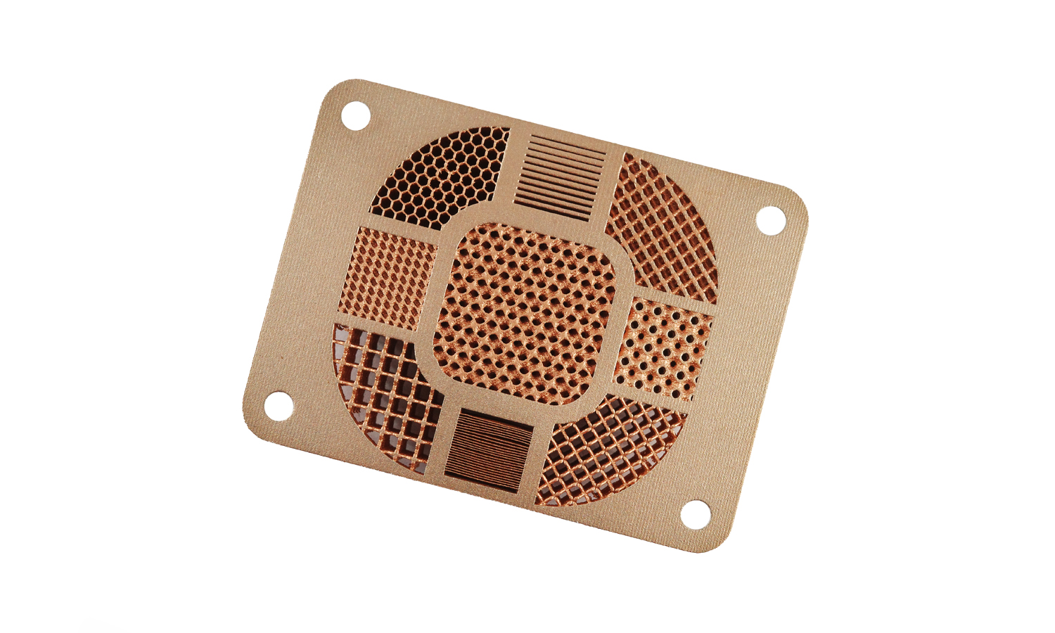
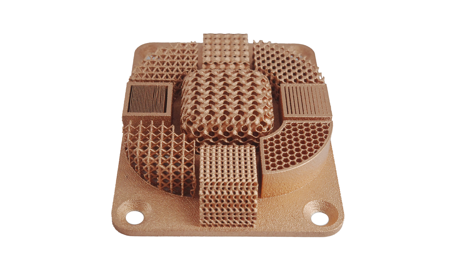
We’re excited to share a fascinating example of what’s achievable with Selective Laser Melting (SLM) 3D printing using pure copper: a rectangular plate showcasing a diverse range of complex geometries. This piece isn’t just visually striking; it highlights the potential of additive manufacturing for creating functional parts with intricate designs.
This copper plate features rounded corners and four strategically placed holes, one at each corner, likely for mounting or fastening. What truly sets this piece apart is its surface, meticulously divided into nine distinct sections. Each section showcases a unique texture or pattern, demonstrating the precision and versatility of SLM technology.
Let’s take a closer look at the diverse geometries incorporated:
- Grid Texture: This classic pattern offers enhanced grip and can be used to reduce glare on surfaces. Imagine its applications in handheld devices or control panels.
- Perforated Texture: Commonly used for ventilation, lightening the material, or enhancing acoustic properties. Think of speaker grilles or lightweight structural panels.
- Wavy Structure: Often employed for aesthetic purposes or to create a specific tactile feel. These structures can also aid in reducing drag or controlling airflow in certain applications.
- Honeycomb Pattern: A favorite in the aerospace and automotive industries for creating lightweight yet robust structural components. This pattern offers an exceptional strength-to-weight ratio.
- Crosshatch Texture: Provides excellent grip and is often found in tool handles and other grip surfaces, ensuring a secure hold.
- Dimples: These indentations can reduce friction and improve fluid dynamics, making them useful in various engineering applications, such as heat sinks or fluid flow management.
- And more! The remaining sections on the plate feature other unique textures and patterns, each with its own potential applications and benefits. These might include gyroid structures, lattice patterns, or custom designs tailored to specific needs.
This sample demonstrates the power of SLM 3D printing to produce parts with complex internal geometries and fine details that would be impossible or prohibitively expensive to manufacture using traditional methods. The use of pure copper adds another layer of value, given its excellent thermal and electrical conductivity, corrosion resistance, and antimicrobial properties.
Interested in exploring the possibilities of pure copper 3D printing for your next project? FacFox offers high-quality pure copper 3D printing services using state-of-the-art SLM technology. We can help you bring your most innovative designs to life, from prototypes to production-ready parts. Contact us today to learn more about our capabilities and how we can assist you in achieving your goals.
Solution
- Step 1: A digital model of the part was designed using CAD (Computer-Aided Design) software. This model contained the precise geometry of the plate, including the rounded corners, holes, and intricate patterns on the surface.
- Step 2: The digital model was then converted into a format suitable for 3D printing, typically an STL file. This process involved slicing the 3D model into thin layers, which the 3D printer would use to build the part layer by layer.
- Step 3: The build chamber of the SLM machine was filled with the copper powder. A thin layer of powder was spread evenly across the build platform.
- Step 4: A laser beam was precisely directed across the powder bed, following the instructions from the sliced digital model. The laser selectively melted the copper powder in the desired areas, fusing the particles together to form a solid layer.
- Step 5: The build platform was then lowered by a small increment, corresponding to the thickness of one layer. A new layer of powder was spread, and the laser melting process was repeated.
- Step 6: These steps were repeated until the entire part was built, layer by layer, from the bottom up. The complex geometries and intricate patterns were created through the precise control of the laser and the layer-by-layer build process.
- Step 7: Once the build was complete, the part was allowed to cool within the build chamber. This cooling process was carefully controlled to minimize stress and distortion in the part.
- Step 8: The excess powder was then removed from the build chamber, and the part was extracted from the platform. This often involved brushing, vacuuming, or other methods to dislodge the loosely sintered powder.
- Step 9: The part was then post-processed, which included steps such as heat treatment to relieve stress or improve material properties, surface finishing to achieve the desired appearance, and potentially cleaning to remove any residual powder.
- Step 10: Finally, the part was inspected to ensure it met the required dimensional accuracy and quality standards. This might involve visual inspection, dimensional measurements, and potentially non-destructive testing methods.


