Material Resin, Rubber
Quantity 130 pcs
Price Range $100-1,000
Lead Time 4 workdays
Gallery
About Project
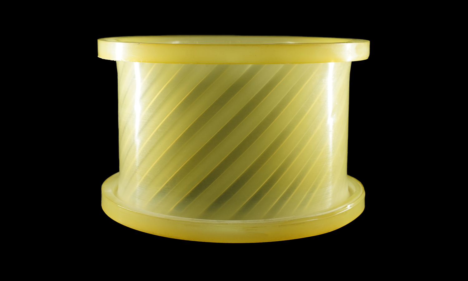
This translucent cylindrical coupler features a finely detailed internal helical pattern, designed to demonstrate both fluid dynamics and torque transfer efficiency. The challenge lay in reproducing its smooth transparency and precise internal geometry without visible layer lines or support marks.
To meet the client’s visual and mechanical requirements, the model was first created digitally and 3D printed as a master pattern using SLA resin printing. SLA technology ensured micron-level precision and an ultra-smooth surface finish suitable for mold replication.
A two-part silicone mold was then produced around the printed master, faithfully capturing the delicate internal spirals. Once the mold cured, it was carefully separated, and the master was removed, leaving a negative cavity ready for resin casting.
Under vacuum conditions, a polyurethane (PU) resin was poured into the mold. The resin was slightly tinted to achieve the desired translucent yellow tone. Vacuum casting removed air bubbles, ensuring optical clarity and uniform wall thickness. After curing, the part was demolded, trimmed, and polished to achieve its final glass-like appearance.
The finished part displays excellent transparency, dimensional accuracy, and elasticity typical of high-grade polyurethane. The seamless surface and clean helical texture highlight the advantages of silicone molding and vacuum casting for complex geometries that demand both function and aesthetics.
Why Choose FacFox for PU Casting
FacFox offers professional PU casting services ideal for producing high-quality prototypes and low-volume end-use parts. With a full range of clear, tinted, rigid, and flexible urethane materials, our vacuum casting team delivers results nearly indistinguishable from injection-molded components.Whether you’re validating design, testing functional performance, or creating visual presentation models, FacFox ensures precision, consistency, and premium surface finish at every step.
Solution
- Step 1 – CAD preparation. The cylindrical coupler with internal helical grooves was modeled in CAD, and critical dimensions and draft allowances were finalized.
- Step 2 – Master printing. A high-resolution master was 3D printed via SLA to capture the spiral texture and ensure a smooth surface suitable for molding.
- Step 3 – Post-processing of master. Supports were removed, the master was wet-sanded/polished through fine grits, and the surface was sealed to improve mold release and optical clarity.
- Step 4 – Mold box setup. The master was fixtured in a mold box with correct parting line selection; gates, vents, and alignment keys were designed and placed.
- Step 5 – Silicone mixing & degassing. Two-part RTV silicone was mixed, vacuum-degassed to remove entrapped air, and poured around the master to form the first half of the mold.
- Step 6 – First half cure. The silicone was allowed to cure fully; the surface was then treated with a release agent at the parting plane.
- Step 7 – Second half molding. Additional silicone was mixed, degassed, and poured to create the second half of the two-part mold; curing was completed.
- Step 8 – Mold opening & master removal. The mold box was disassembled, the silicone halves were separated, and the SLA master was removed to reveal the negative cavity.
- Step 9 – PU resin preparation. Two-part polyurethane resin was measured by weight; a translucent yellow tint and UV-stabilizer were added as specified. The mixture was stirred and vacuum-degassed.
- Step 10 – Casting under vacuum. The silicone mold was assembled, sealed, and placed in a vacuum chamber. The PU resin was poured through the gate while under vacuum to minimize bubbles and ensure uniform wall thickness.
- Step 11 – Pressure/thermal cure. The filled mold was transferred to a pressure/oven environment as required by the resin’s datasheet, and curing was completed to full hardness.
- Step 12 – Demolding. After cure, the mold was opened and the cast part was carefully extracted to avoid deforming the helical features.
- Step 13 – Gate/flash removal. Gates and vents were trimmed; minimal flash was removed with fine tools, and edges were dressed.
- Step 14 – Finishing for clarity. The outer and inner surfaces were polished as needed (progressive wet sanding and plastic polish), and an anti-yellowing clear coat was optionally applied.
- Step 15 – Dimensional inspection. Key dimensions (OD, ID, length, wall thickness, and helix pitch) were measured; visual inspection for inclusions and bubbles was performed.
- Step 16 – Cleaning & packaging. The part was cleaned, dust-free packed with protective wraps, and labeled for shipment.


