Material Rubber
Quantity 1 pcs
Price Range $100-1,000
Lead Time 2 workdays
Gallery
About Project
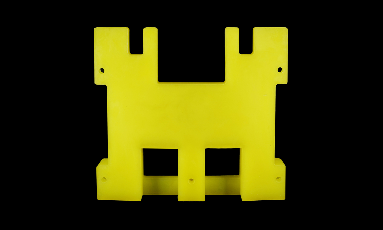
Bright yellow, tough, and quietly doing the hard work, this PU guide plate is a good example of why polyurethane shows up all over automation and material handling.
Guide plates are the ŌĆ£keep everything on trackŌĆØ parts inside equipment. They help align products, stabilize motion, and prevent unwanted rubbing between moving assemblies. In this design, the broad flat face provides a smooth guiding surface, while multiple through-holes make it easy to clamp onto a metal bracket or backer. The U-shaped slots are a practical detail too: they can help the plate locate onto pins during installation, making assembly faster and reducing the chance of misalignment. Two square windows reduce weight and material while keeping stiffness where the fasteners and contact loads matter most. The extra material around the main holes also helps resist deformation from repeated tightening and vibration.
PU is a natural fit for this kind of job. ItŌĆÖs abrasion resistant, impact tolerant, and more forgiving than metal when parts slide or bump against it. It also helps cut noise and vibration, and it reduces the risk of scratching or denting the components it guides. For equipment that runs long hours, a replaceable PU guide plate can be a simple way to extend service life and reduce downtime.
If you need PU parts like this made reliably, FacFox can help. We offer PU manufacturing services for functional end-use components, from clean-cut plates to more complex custom geometries, with consistent dimensions and solid surface quality. Send us your drawing or 3D model, and weŌĆÖll recommend a practical process and deliver parts ready to install.
Solution
- Step 1: The CAD file and 2D drawing were reviewed, and critical dimensions, hole positions, and tolerances were confirmed.
- Step 2: A PU sheet or block in the specified hardness and color was selected, and the material certificate and batch information were recorded.
- Step 3: The blank was cut to an oversized rectangle, and clamping faces were prepared for stable machining.
- Step 4: The blank was fixtured on a CNC bed, and the outer profile was milled to the final contour.
- Step 5: The two U-shaped slots were milled, and the slot widths and radii were controlled to match the locating pins.
- Step 6: The square windows were pocket-milled and through-cut, and internal corners were finished to the required radius.
- Step 7: All through-holes were drilled to size, and position accuracy was maintained using the programmed toolpath and locating references.
- Step 8: Edges were deburred, and light chamfers were applied to reduce handling damage and prevent tearing at sharp corners.
- Step 9: The part was cleaned to remove chips and residue, and the surface was inspected for burns, tool marks, and defects.
- Step 10: Final inspection was completed using calipers and gauges, and the dimensions and hole locations were verified against the drawing.
- Step 11: The guide plate was packaged with protective wrapping, and the shipment was prepared to avoid deformation during transport.


