Gallery
About Project
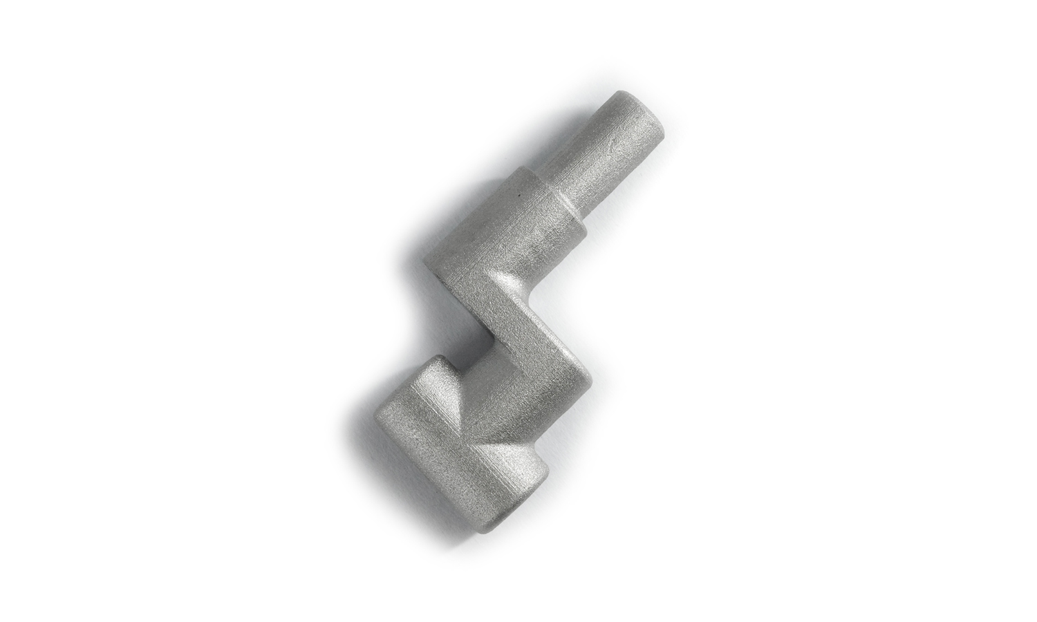
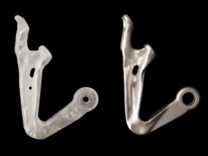
Meet the BinderJet 3D Printed SS316L Right-Angle Bend, a versatile metallic component engineered for precision and durability. Crafted using advanced BinderJet 3D printing technology, this component is designed to meet the demanding needs of various mechanical assemblies.
Key Features
- Material: Made from high-quality SS316L stainless steel, ensuring exceptional strength and corrosion resistance.
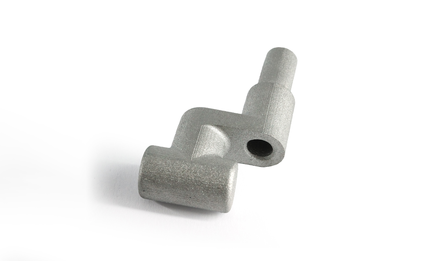
- Finish: The component features a matte raw finish, giving it a robust and industrial look.
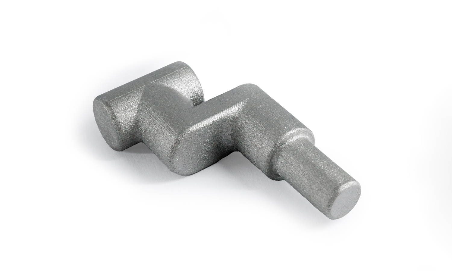
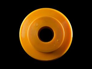
- Design: Both ends of the component are cylindrical, providing versatile attachment points. A precise right-angle bend in the middle enhances its functionality in mechanical assemblies. The presence of a blind hole in the middle of the component adds to its versatility, potentially serving as a pivot point or attachment area.
Functional Applications
This metallic component could play a crucial role in various mechanical assemblies, potentially serving as a crank or a lever. The precise shape and the inclusion of the blind hole indicate its ability to transmit rotational motion or connect different parts of a machine effectively.
Why Choose FacFox’s Metal 3D Printing Services?
Experience unparalleled precision and quality with FacFox’s BinderJet metal 3D printing services. FacFox specializes in producing high-performance metal components like the SS316L Right-Angle Bend, ensuring exceptional accuracy and durability. Whether you need intricate mechanical parts, custom designs, or functional prototypes, FacFox’s state-of-the-art 3D printing technology delivers outstanding results tailored to your specific needs. Trust FacFox to bring your innovative ideas to life with unmatched efficiency and expertise.
Solution
- Step 1: 3D Model Creation.┬ĀA 3D CAD model of the right-angle bend was designed using specialized software.
- Step 2: Data Slicing.┬ĀThe 3D model was sliced into 2D cross-sections, creating layer-by-layer instructions for the printer.
- Step 3: Powder Bed Preparation.┬ĀA thin layer of stainless steel (SS316L) powder was spread evenly across the build platform.
- Step 4: Binder Jetting. A printhead selectively deposited a liquid binder onto the powder, adhering particles together to form the desired shape. This process was repeated layer by layer, building up the component.
- Step 5: Debinding. The printed component was removed from the build platform and placed in a debind chamber. The binder was removed from the part using a thermal or solvent-based process.
- Step 6: Sintering. The debinded component was placed in a high-temperature furnace. The powder particles were fused together, creating a solid, dense metal part.
- Step 7: Post-Processing. The sintered component was cleaned to remove any residual powder. Machining or other finishing processes were applied, if necessary, to achieve the final desired dimensions and surface finish.
- Step 8: Quality Inspection. The finished component was inspected to ensure it met the required quality standards, including dimensional accuracy and surface finish.

