SLS 3D Printed Black Nylon Automotive Mirror Housing Prototype

SLS 3D Printed Black Nylon Automotive Mirror Housing Prototype

facfox-case-study
Process 3D Print
Material Plastic
Quantity 1 pcs
Price Range $1-100
Lead Time 5 workdays

Gallery

About Project

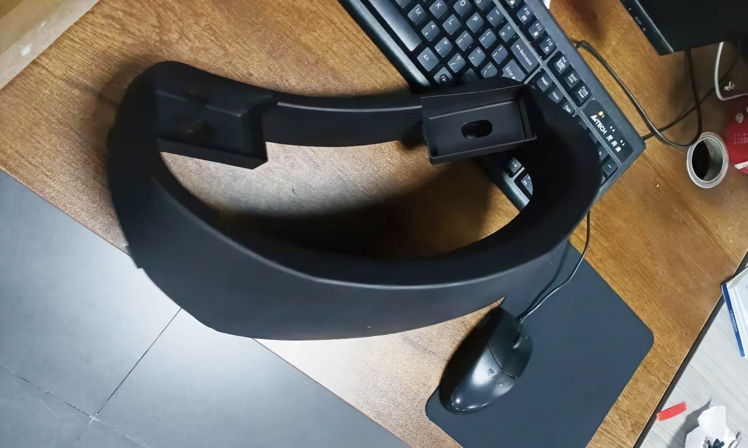
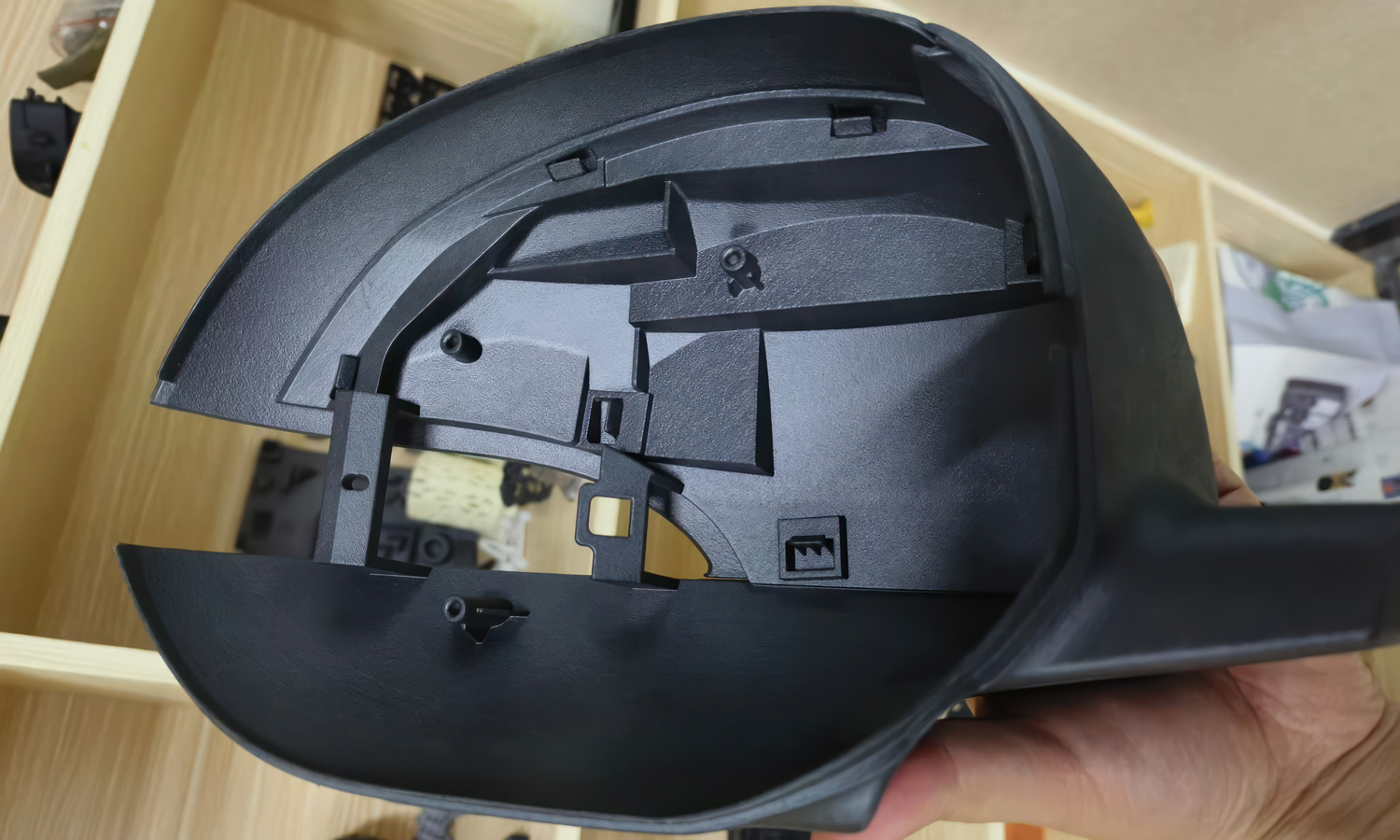
This black nylon exterior mirror housing prototype supports reverse engineering, assembly evaluation, and dimensional review before tooling development. SLS printing reproduces the curved shell and detailed internal features, while 3D scanning provides feedback for subsequent design iterations. Contact FacFox or upload your 3D files for a quote.

Challenge

This exterior mirror housing combines a curved outer profile with internal clips, locating holes, bosses, ribs, and mounting features. Reproducing the overall shape was only part of the task: the prototype also needed to preserve the interfaces that determine how it fits with adjacent mirror components. Its open frame and extended edges made dimensional control especially important during printing, cooling, and handling.

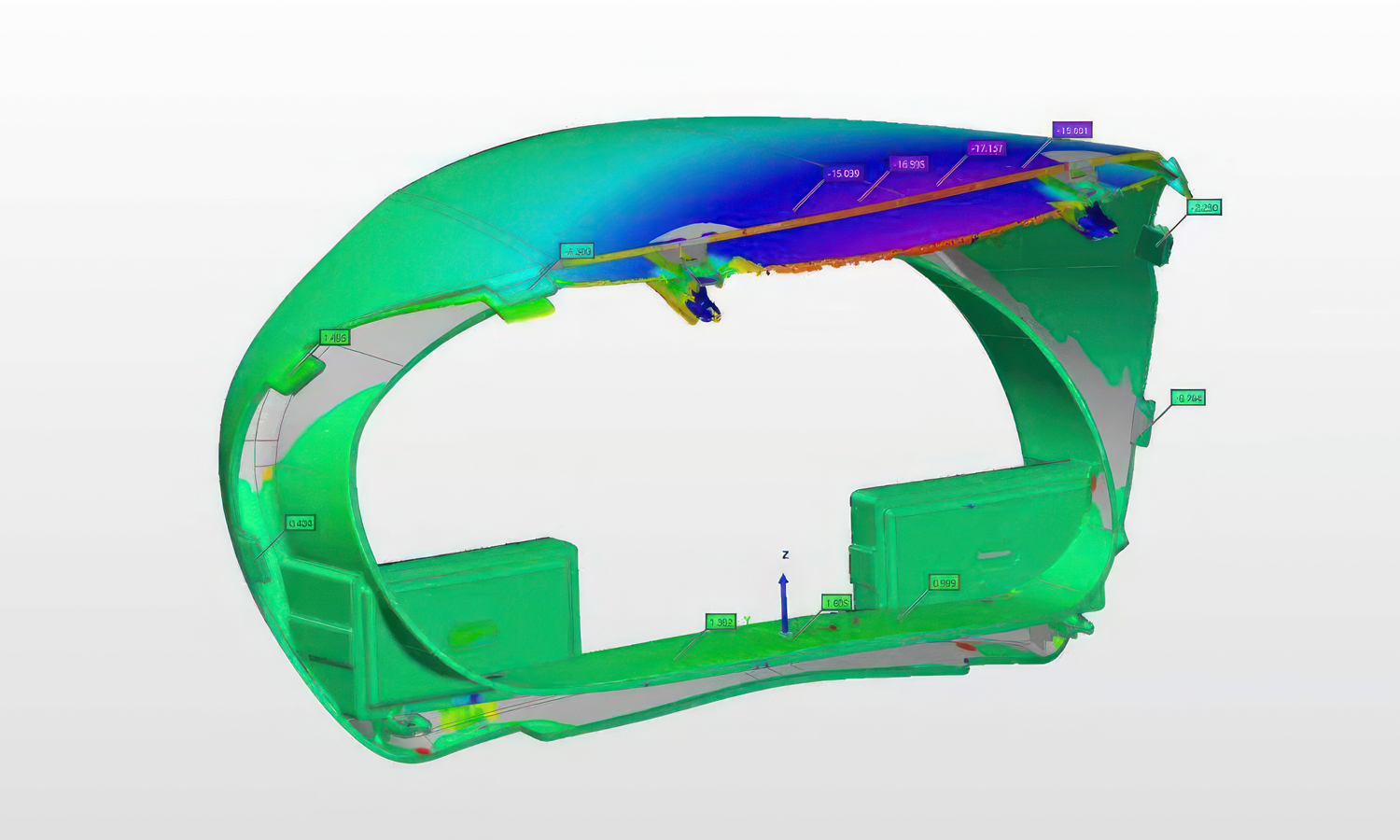
Scan-to-CAD comparison added another challenge: interpreting the measured differences correctly. The supplied deviation map shows a pronounced negative region along the upper edge. Alignment, reference geometry, scan coverage, and measurement conditions must be reviewed before attributing this pattern to manufacturing distortion or using it for compensation.
Solution

  • Step 1: Recommend a suitable process and material based on the client’s requirements and budget, assess printing and assembly risks, and discuss necessary model revisions with the client.
  • Step 2: Capture the reference component geometry for reverse engineering, reconstruct the CAD surfaces and internal interfaces, and define the mounting datums and dimensions requiring inspection.
  • Step 3: Review the shell thickness, ribs, clips, bosses, locating holes, and mating edges. Adjust fragile features and assembly clearances where needed for the nylon prototype.
  • Step 4: Produce the housing using SLS nylon with a black finish, selecting build orientation and thermal controls to manage distortion around the open frame and extended rim.
  • Step 5: Allow controlled cooling before unpacking, remove loose powder from the cavities and small features, and clean the surfaces while preserving the locating and mating geometry.
  • Step 6: Trial-fit the prototype with the relevant mirror components, checking clip engagement, hole positions, edge clearances, and interference without forcing the shell into position.
  • Step 7: Scan the prototype under documented measurement conditions and align the scan with the correct CAD revision using an agreed datum or alignment method. Generate a deviation map and inspect the mounting features separately.
  • Step 8: Investigate the upper-edge deviation by checking alignment, scan quality, free-state versus constrained shape, and thermal distortion. Revise geometry or process settings only after confirming the cause, then repeat printing, fitting, and inspection against the agreed acceptance criteria.