Gallery
About Project
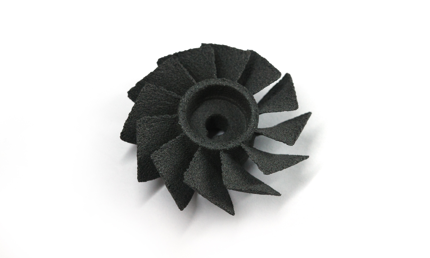
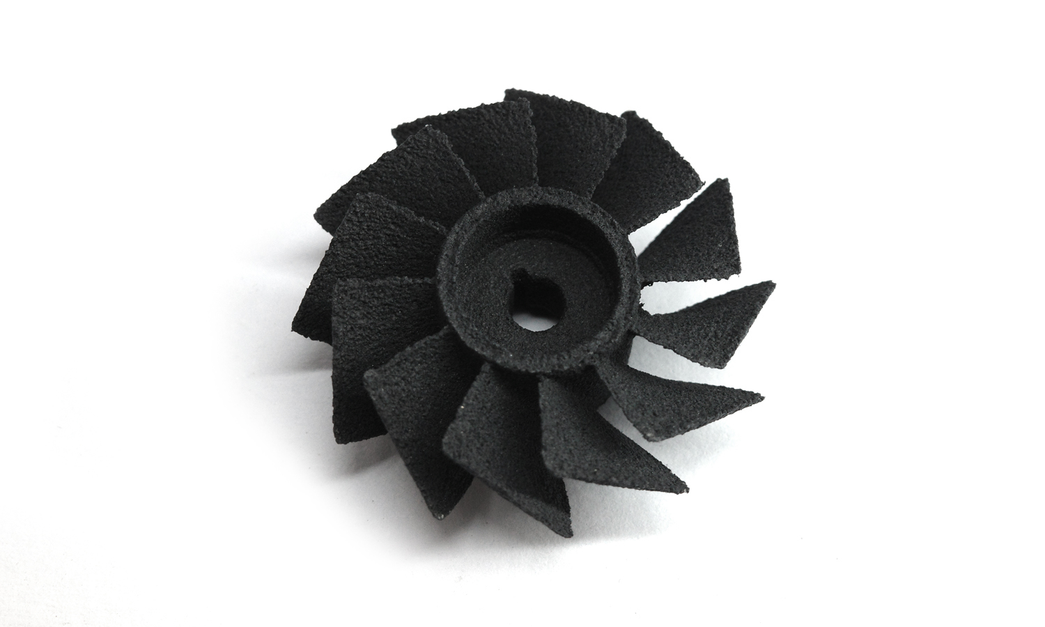
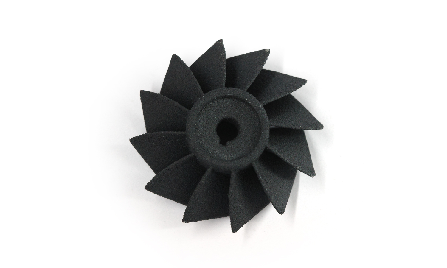
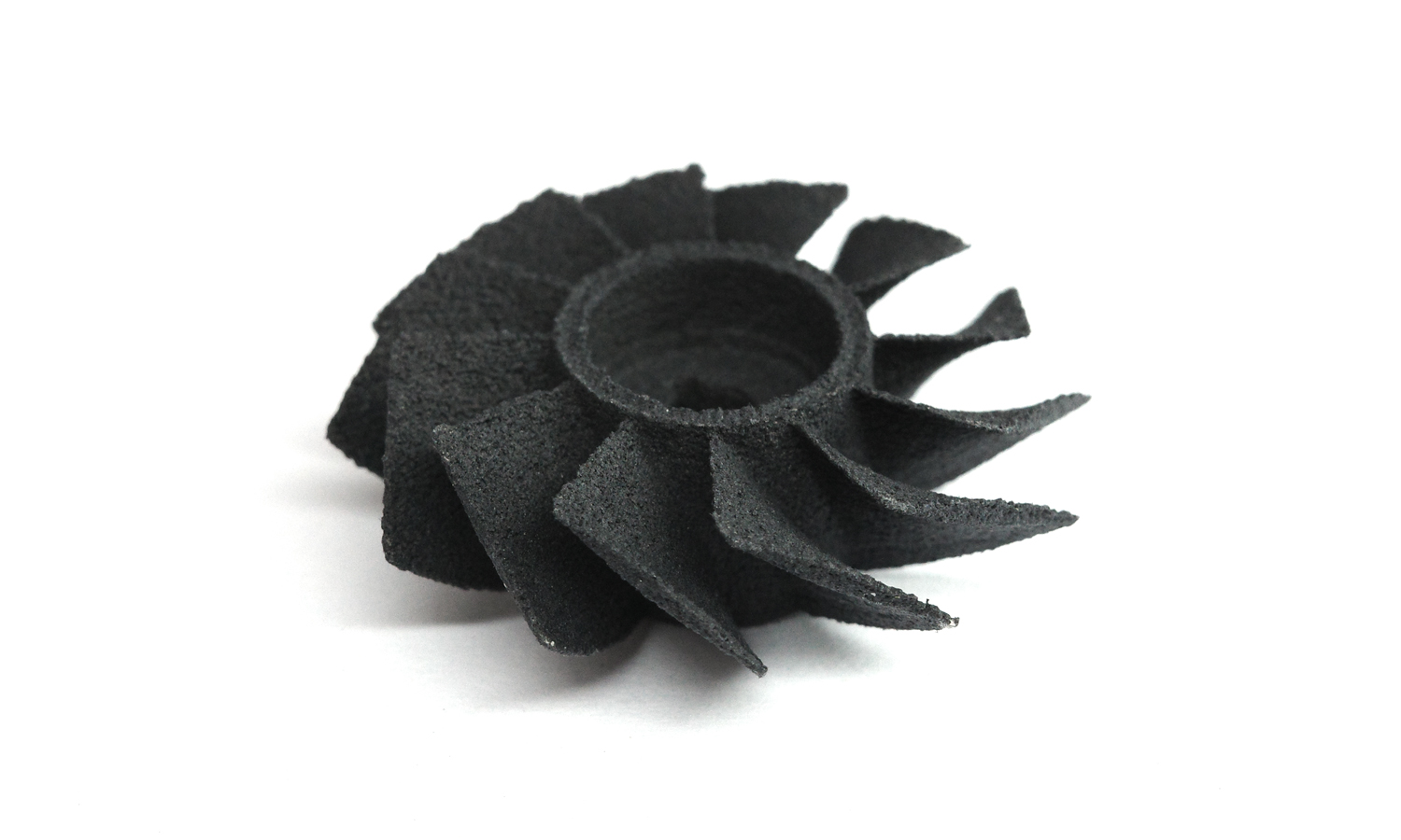
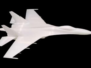
3D printing opens up incredible possibilities for creating intricate models, and this SLS-printed PA 11 CF propeller miniature is a testament to that. However, a closer examination reveals some important considerations when working with this material and process, especially for miniatures.
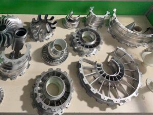
- Accurate Form: The overall shape and dimensions of the propeller are faithfully reproduced. The central hub and blade spacing are well-defined.
- Granular Finish: The surface has a characteristic grainy texture, typical of SLS printing. This might not be ideal for those seeking a smooth, highly detailed finish.
- Edge Sharpness: The edges appear slightly rounded, lacking the crispness desired in a miniature, particularly around the blades.
- Tip Detail: Some of the fan tips seem blunt or even broken, which detracts from the overall impression.
While PA 11 CF offers excellent strength and durability, it might not be the optimal choice for miniatures where fine details are paramount. The granular nature of SLS printing and the challenges in achieving sharp edges with this material can limit the level of intricacy achievable.
For miniature enthusiasts seeking higher resolution and finer details, alternative materials and printing processes like resin 3D printing might be more suitable.
Despite the limitations highlighted in this example, FacFox offers a wide range of nylon 3D printing services for various applications. If you’re looking for strong, durable parts with complex geometries, FacFox’s expertise in SLS printing and their selection of nylon materials can provide excellent solutions. Contact FacFox today to discuss your project requirements and explore the possibilities!
Solution
- Step 1: CAD Model Preparation. A 3D model of the propeller was designed using CAD software.
- Step 2: File Export. The design was exported in a suitable file format (e.g., STL).
- Step 3: Printing Preparation. The STL file was imported into slicing software, and the build parameters were configured (layer height, material, etc.).
- Step 4: Powder Bed Preparation. A thin layer of nylon powder was deposited onto the build platform within the SLS machine.
- Step 5: Selective Laser Sintering. A high-powered laser was used to selectively scan and sinter the powder according to the cross-sectional geometry of the propeller design.
- Step 6: Layer Repetition. Steps 4 and 5 were repeated layer by layer until the entire propeller was built.
- Step 7: Cooling. The build chamber was allowed to cool down gradually.
- Step 8: Part Retrieval. The printed propeller was carefully extracted from the powder bed.
- Step 9: Excess Powder Removal. Loose powder was removed from the propeller using brushes and/or compressed air.
- Step 10: Post-Processing (Optional). Depending on the desired finish, the propeller may have been further processed (e.g., bead blasted for a smoother surface).

