
Material Resin
Quantity 1 pcs
Price Range $1-100
Lead Time 2 workdays
Gallery
About Project
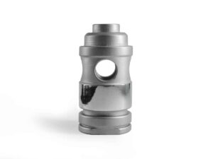
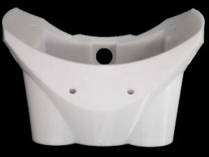
This project features a custom centering spacer designed to stabilize a cylindrical component within a housing. The part was modeled with a split-body design that allows it to snap around an existing shaft, eliminating the need for end-to-end assembly. Four internal fins ensure perfect concentric alignment, while the curved outer “petals” maintain stable contact with the outer casing.
To meet performance requirements-dimensional accuracy, rigidity, and smooth load distribution-the spacer was produced using Flashforge Rigid Resin, a material known for its stiffness and precise surface finish. Its crisp edges and consistent geometry enabled the spacer to perform like a machined part while remaining lightweight and economical. Even with the complex interlocking features and non-uniform cross-sections, the resin maintained excellent detail and stability.
The finished component demonstrated strong mechanical integrity, clean mating surfaces, and a reliable fit within the client’s assembly. Because it is fully 3D-printed, design adjustments such as wall thickness, fin geometry, and split-line tolerances can be quickly iterated without the costs typically associated with machining or injection molding.
This case highlights how additive manufacturing excels in producing functional mechanical components that require both accuracy and geometry-specific performance. Centering spacers, alignment collars, sensor mounts, vibration-isolating inserts, and other custom internal supports often come with difficult shapes-internal channels, complex curves, or snap-fit structures-that traditional methods struggle to produce efficiently.
Bring Your Engineering Parts to Life with FacFox
FacFox specializes in delivering precision 3D-printed mechanical parts across resin, nylon, and engineering polymer technologies. Whether you need a one-off prototype, a production-ready alignment fixture, or custom inserts for robotics, automation, or industrial equipment, our team provides:
- High-accuracy SLA and DLP resin printing
- Tough nylon SLS and MJF for durable engineering components
- Professional engineering review and manufacturability feedback
- Reliable turnaround for both prototypes and batch production
If your project involves complex geometry, tight tolerances, or functional performance, FacFox can help you build it quickly and cost-effectively. Reach out anytime – we’re ready to support your next engineering challenge.
Solution
- Step 1: CAD modeling. The centering spacer was designed in CAD software according to the specified inner and outer diameters, with the split-line, internal fins, and snap features carefully defined.
- Step 2: File preparation. The 3D model was exported as an STL file and was imported into the slicing software. Orientation, layer height, and support structures were set to balance strength, surface quality, and print time.
- Step 3: Printer setup. A Flashforge resin printer was prepared, and the vat was filled with Flashforge Rigid Resin. The build platform was leveled and was cleaned to ensure proper adhesion.
- Step 4: 3D printing. The sliced file was sent to the printer, and the part was built layer by layer. Each layer was cured by UV light until the full height of the spacer was reached.
- Step 5: Part removal. After printing, the build platform was removed from the machine, and the centering spacer was detached from the platform with a scraper.
- Step 6: Cleaning. Excess uncured resin was washed off in an isopropyl alcohol bath. The part was then left to dry in a dust-free environment.
- Step 7: Post-curing. The cleaned spacer was placed in a UV curing chamber and was post-cured for the recommended time to reach full mechanical strength and dimensional stability.
- Step 8: Support removal and deburring. All support structures were carefully removed with hand tools. Edges and contact surfaces were lightly deburred so that sharp artifacts were eliminated.
- Step 9: Dimensional inspection. Critical dimensions, such as inner diameter, fin thickness, and overall roundness, were measured with calipers and gauges. The part was confirmed to be within tolerance.


