Gallery
About Project
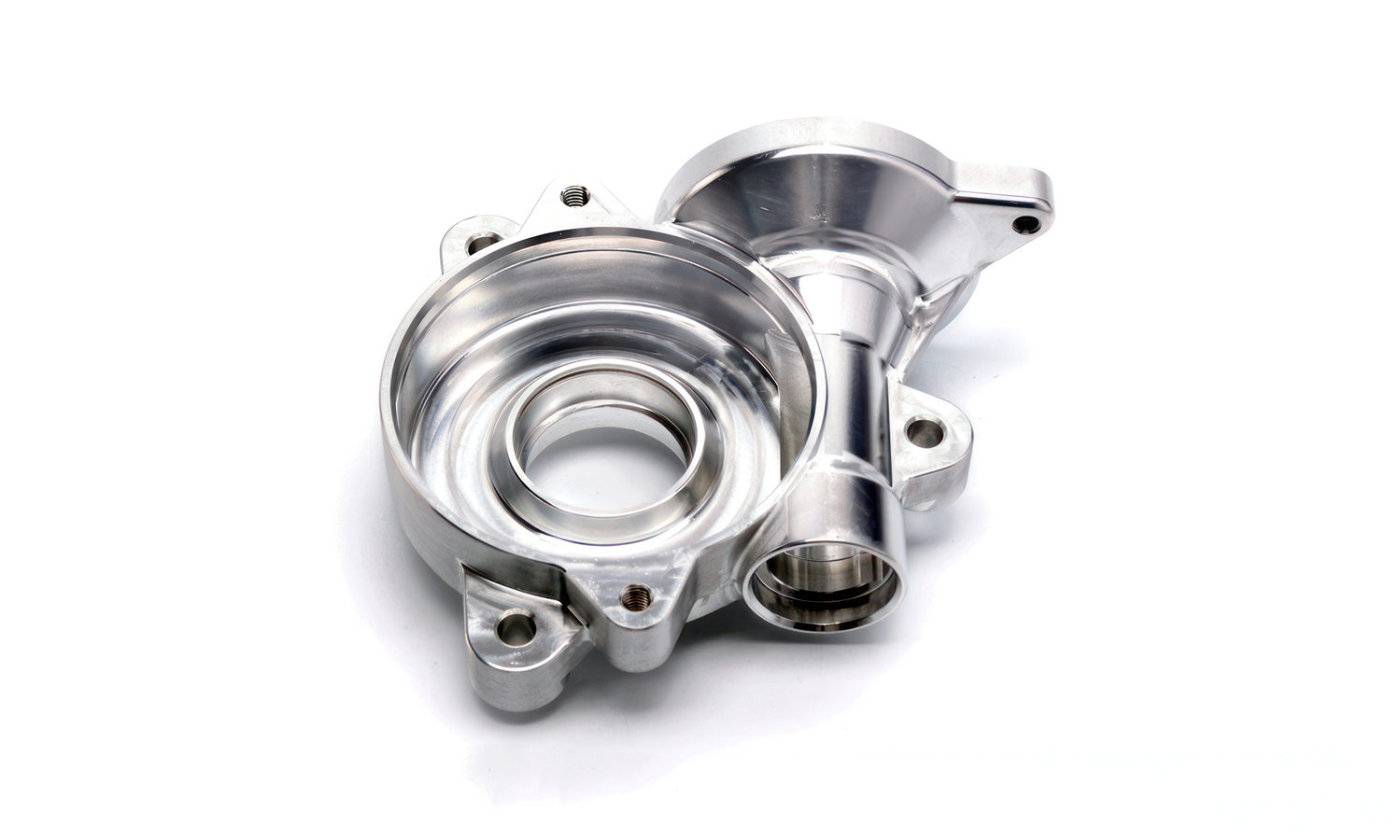
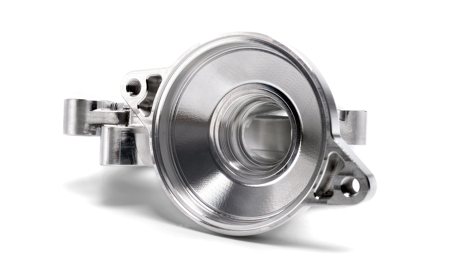
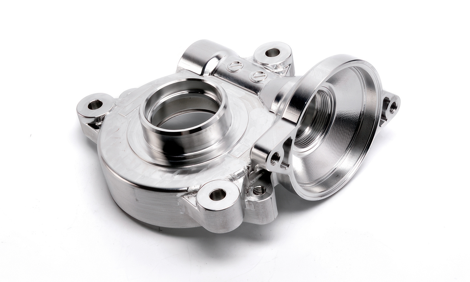
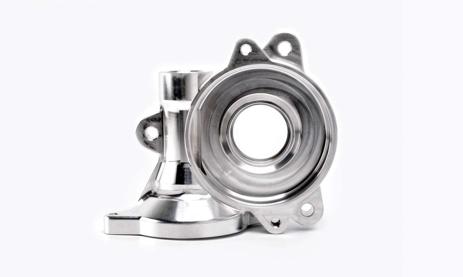
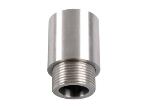
This high-performance aluminum housing is a masterclass in modern manufacturing. Based on its intricate volute geometry and stepped central bores, itŌĆÖs designed to serve as a turbocharger compressor cover or a high-efficiency centrifugal pump housing.
The part features a complex scroll-shaped interior to optimize fluid dynamics, converting kinetic energy into pressure with minimal loss. You can even see the fine tool paths from the CNC milling process, highlighting the tight tolerances required for the high-speed rotating assembly that lives inside. Whether itŌĆÖs managing airflow for a boosted engine or circulating coolant in an industrial system, this component is built to handle the heat and the pressure.
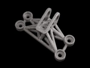
Precision like this is what sets great products apart. At FacFox, we specialize in bringing these complex geometries to life. While this piece showcases our CNC expertise, our Metal 3D Printing (DMLS) services allow you to push boundaries even furtherŌĆöcreating internal cooling channels and lightweight structures that are impossible to machine. From rapid prototypes to low-volume production, weŌĆÖre here to help you build the future.
Ready to start your next project? Upload your CAD files to FacFox.com for an instant quote today!
Solution
- Step 1: The high-grade aluminum alloy billet was selected and inspected for structural integrity.
- Step 2: The workpiece was securely mounted onto a multi-axis CNC milling machine using a specialized fixture.
- Step 3: The primary volume was removed through a roughing process to establish the basic volute and flange shapes.
- Step 4: The complex internal scroll geometry and central bearing seats were precision-machined using high-speed ball-end mills.
- Step 5: The mounting holes and internal threads were drilled and tapped according to the exact CAD specifications.
- Step 6: The critical mating surfaces were fine-tuned to achieve the required flatness and micron-level tolerances.
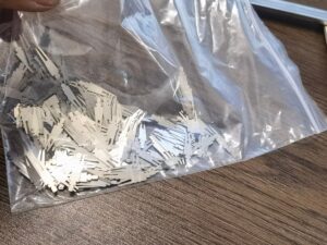
- Step 7: The finished part was deburred and cleaned to remove any residual metal shavings or coolant.
- Step 8: A final quality inspection was performed using a Coordinate Measuring Machine (CMM) to verify dimensional accuracy.

