- ColorJet 3D Printed Full-color Bear Holding a Balloon Statue
- SLA 3D Printed Celestial Wheel Ceiling Medallion Pub Decor Customization
Material Plastic
Quantity 1 pcs
Price Range $100-1,000
Lead Time 4 workdays
Gallery
About Project
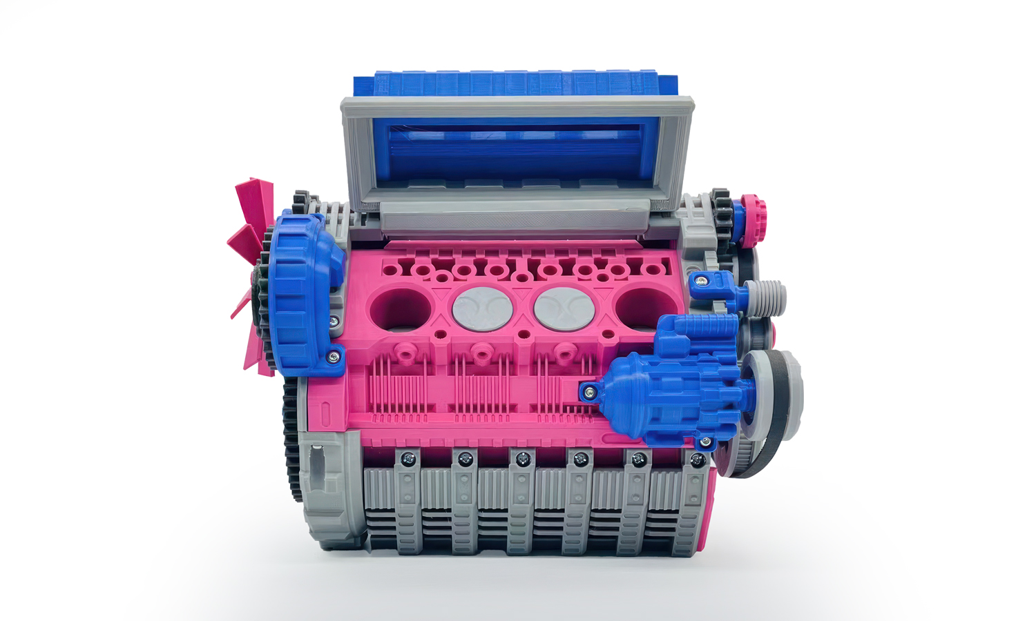
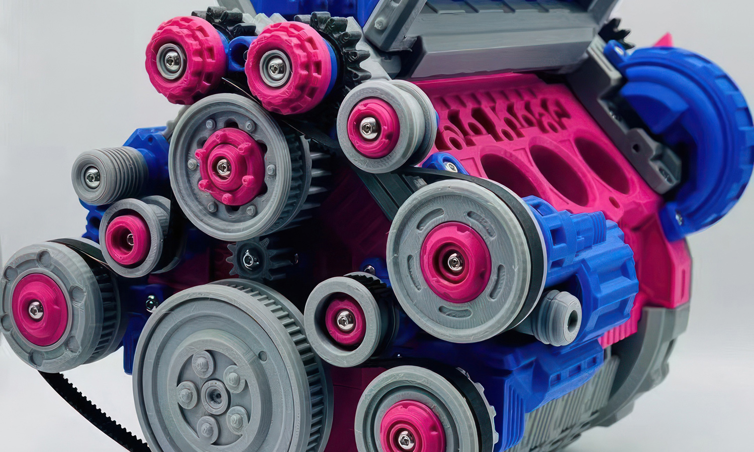
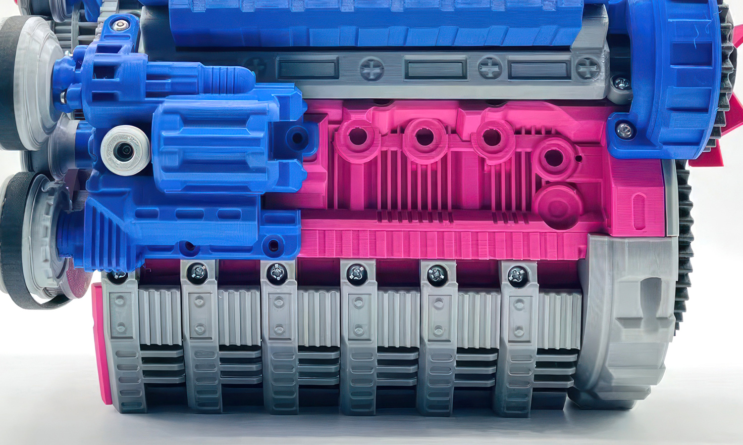
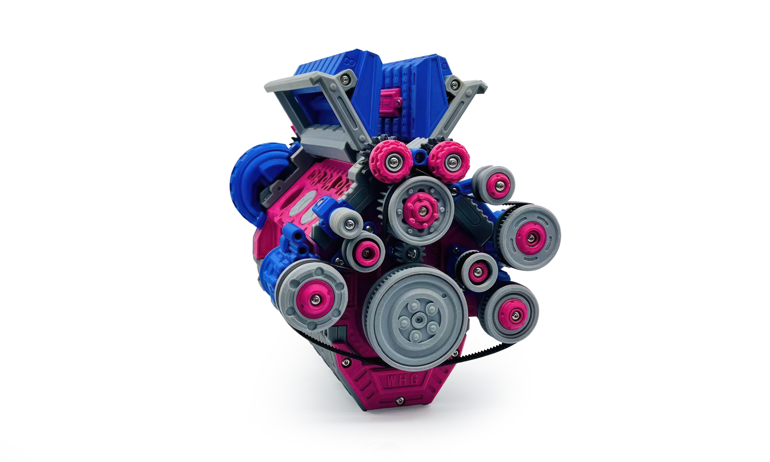
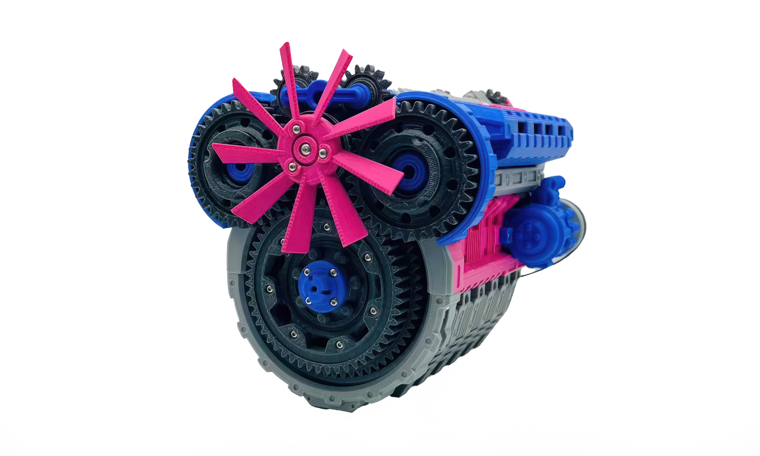
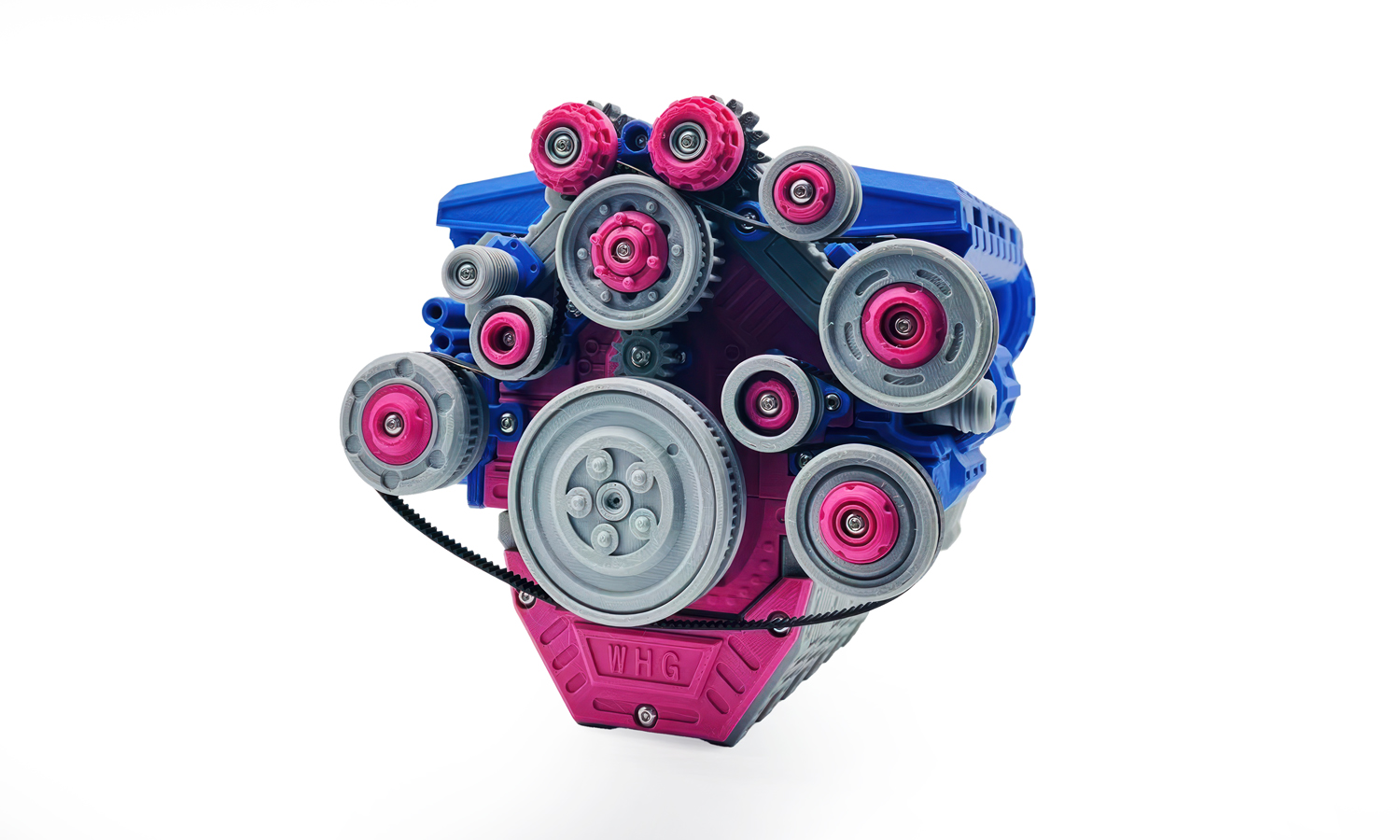
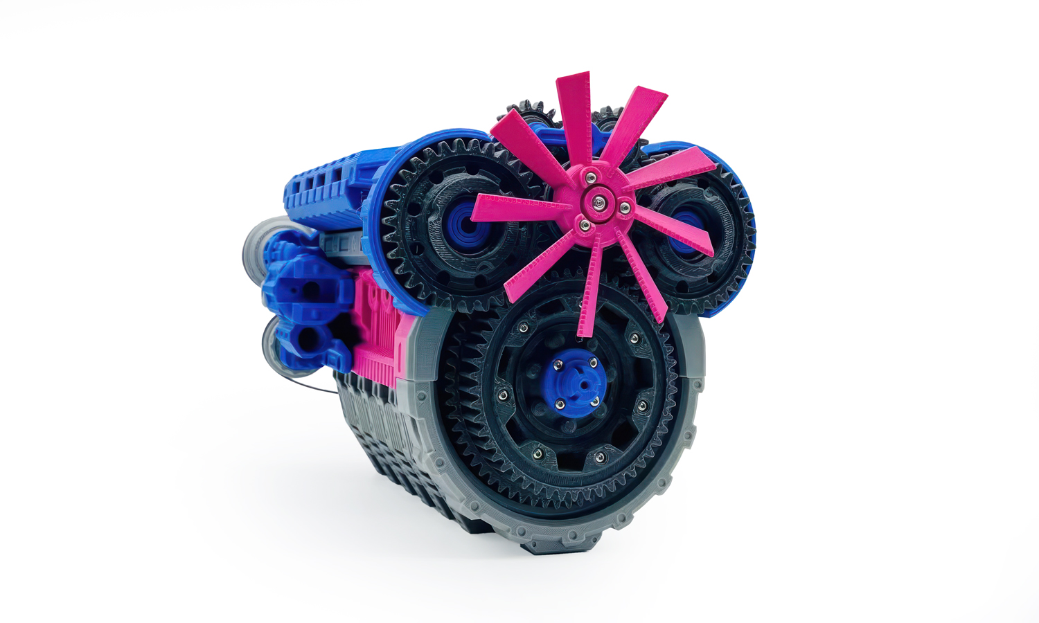
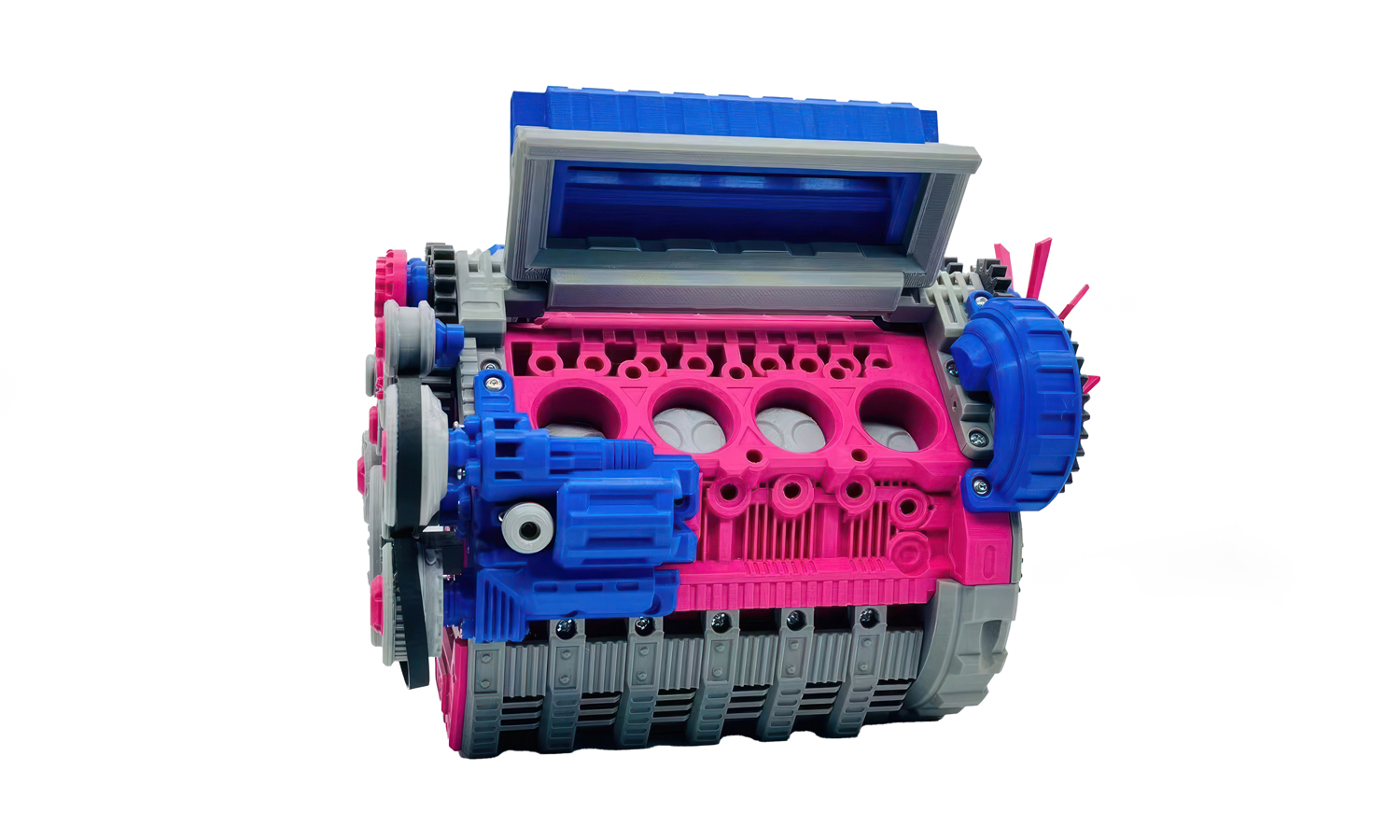
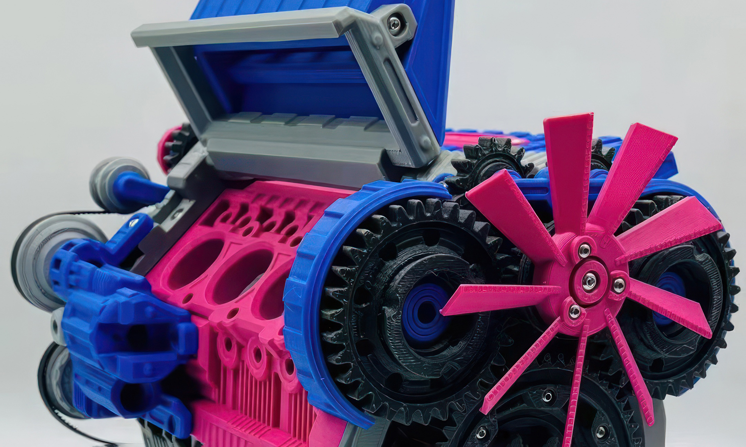
This vibrant 3D printed model offers a captivating glimpse into the intricate world of internal combustion engines. Crafted with precision, the model showcases various components in distinct colors: pink, blue, gray, and black. This color-coding not only enhances visual appeal but also aids in identifying different parts and their functions.
From detailed pistons to a realistic fan, the model accurately represents the key elements of an engine. Its simplified structure makes it easy to understand the complex interplay between these components.
But the real magic lies in its moving parts! The pistons, crankshaft, and fan are designed to simulate the actual motion of an engine. This dynamic display brings the model to life, providing a hands-on learning experience.
Whether you’re an engineering enthusiast or simply curious about how engines work, this 3D printed model is a fascinating educational tool. It’s a testament to the power of 3D printing in creating intricate and functional models.
Want to bring your own 3D designs to life? FacFox offers a wide range of 3D printing services, including FDM, SLA, SLS, and more. Our expert team can help you transform your ideas into tangible objects. Visit our website to learn more about our capabilities and to get a quote for your next project.
Solution
- Step 1: The blueprints for the internal combustion engine model were downloaded from the internet. A manual for assembly was provided alongside the blueprints.
- Step 2: The various components of the engine model were 3D printed using a range of colored plastics.
- Step 3: Each part was carefully removed from the printer and any support material was cleared away.
- Step 4: The printed parts were then sanded and cleaned to ensure a smooth finish and proper fit.
- Step 5: Bolts, nuts, and other fastening parts were collected as specified in the assembly manual.
- Step 6: The assembly process began by following the detailed instructions provided in the manual.
- Step 7: Moving parts, such as pistons and the crankshaft, were precisely fitted into place.
- Step 8: Bolts and nuts were used to secure the parts together, ensuring stability and functionality.
- Step 9: The fan and other external components were attached, completing the model.
- Step 10: Final adjustments and checks were made to ensure all parts moved smoothly and correctly.
- Step 11: The completed model was inspected for quality and accuracy, ready to demonstrate the principles of an internal combustion engine.
