Gallery
About Project
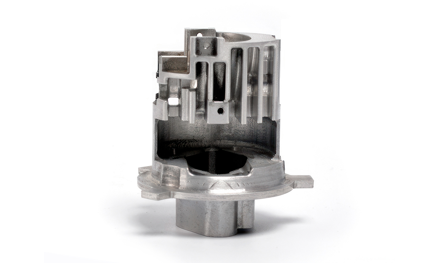
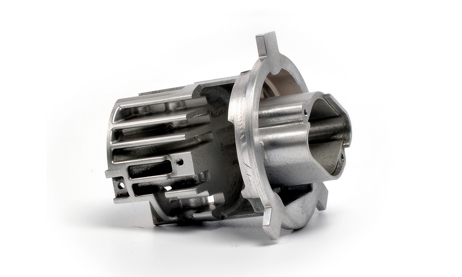
Precision and performance go hand in hand when it comes to motion control systems, and the stepper motor housing is no exception. This CNC-machined aluminum component is engineered to ensure accurate alignment, thermal management, and long-term durability in demanding environments.
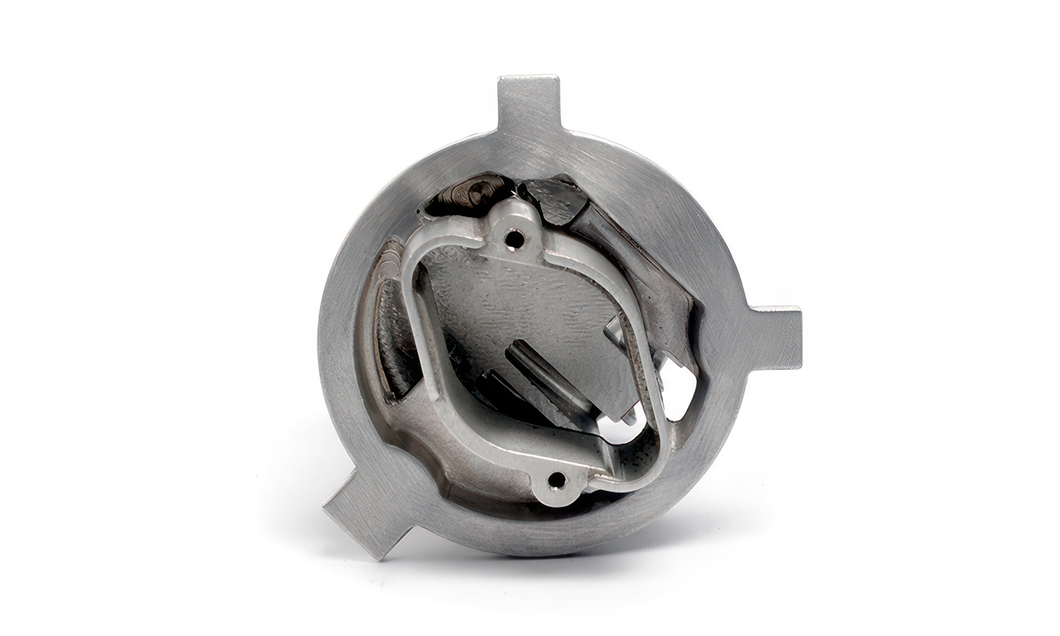
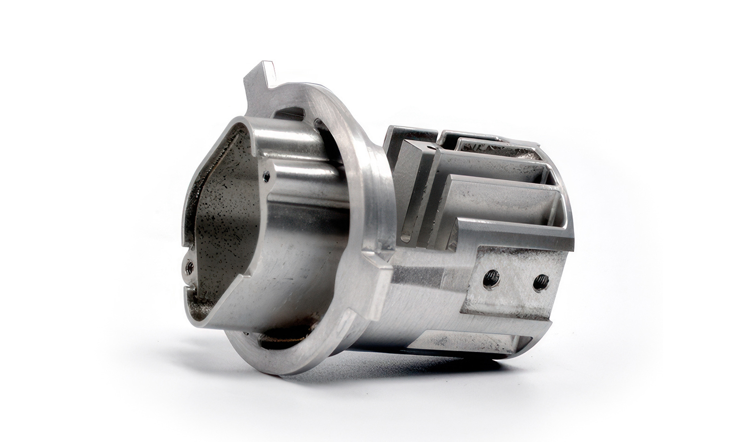
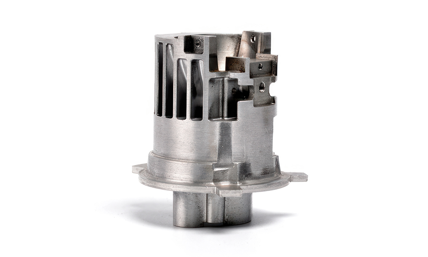
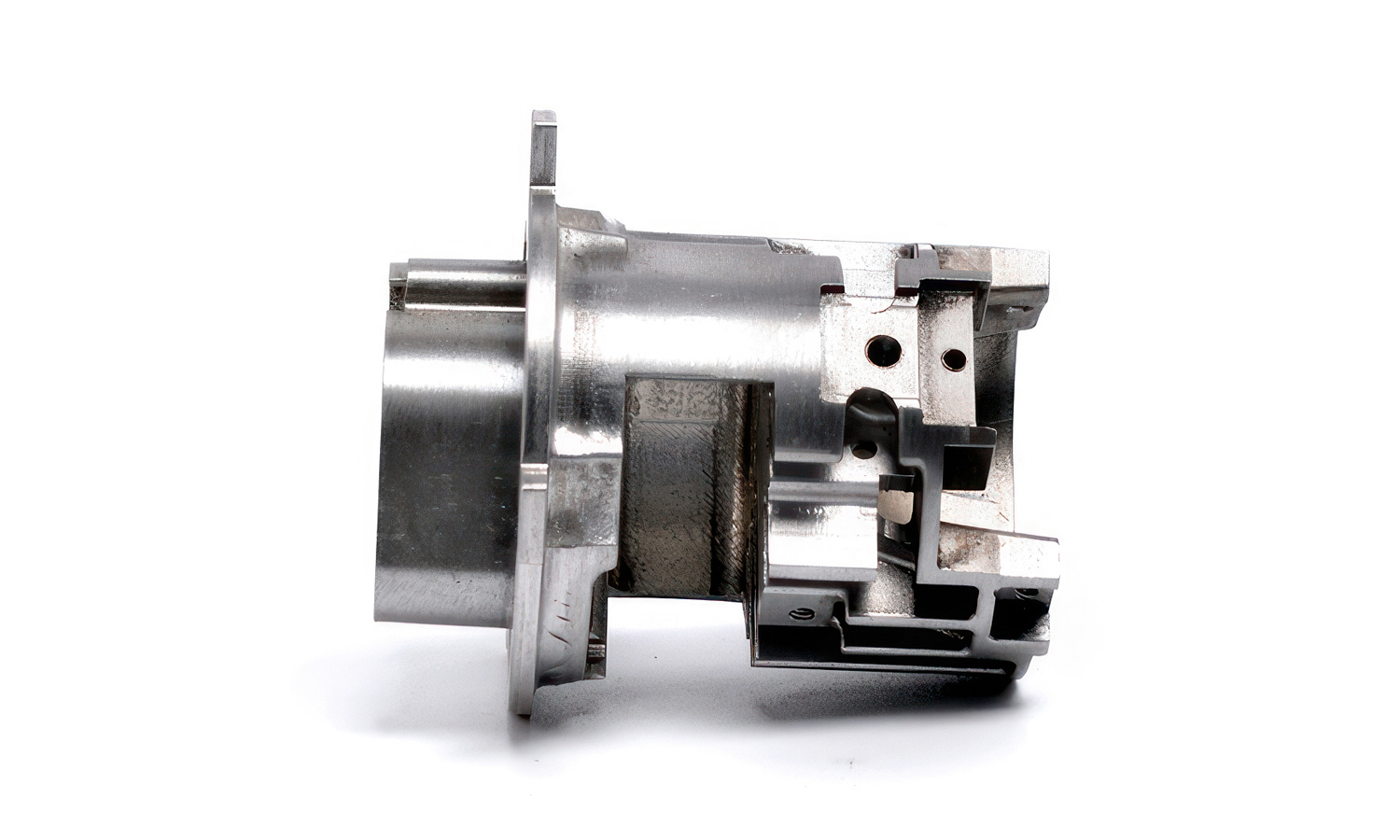
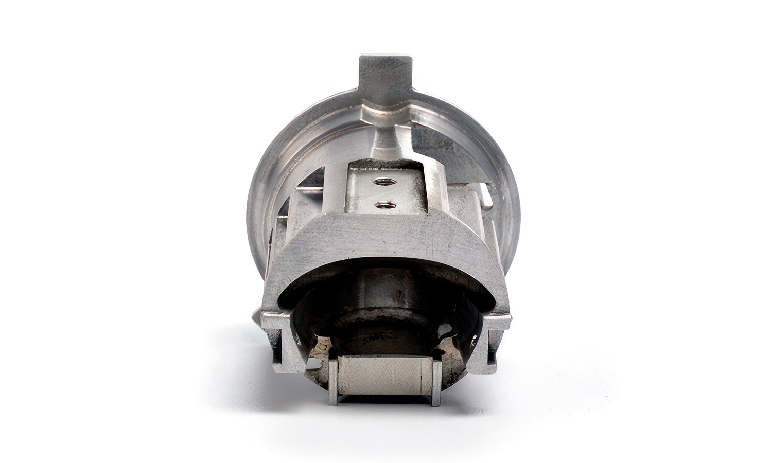
Crafted from high-grade aluminum alloy, the housing features complex geometries that include bearing seats, mounting flanges, and structural ribs. These elements aren’t just aesthetic – they play a critical role in heat dissipation, load-bearing, and vibration reduction. Internal bores are finished to tight tolerances to accommodate rotor assemblies and support smooth, friction-reduced operation. Threaded ports and pockets are precisely placed to enable easy integration with other system components such as gearboxes or timing belt pulleys.
Thanks to multi-axis CNC machining, every feature is produced with exceptional precision. The machining process ensures that critical surfaces – especially those in contact with bearings and shafts – meet strict concentricity and flatness requirements. This level of accuracy is vital for minimizing motor noise and wear, and for ensuring reliable, repeatable motion.
This type of housing is commonly used in robotics, 3D printers, automated machinery, and CNC systems – wherever compact, high-torque, and accurate stepper motors are needed. With a design focused on both mechanical performance and thermal efficiency, it serves as a cornerstone for reliable mechatronic systems.
Looking for precision motor components?
At FacFox, we offer CNC machining services capable of producing high-precision parts like this stepper motor housing. Our advanced equipment, tight tolerance control, and engineering expertise ensure you get the right part – every time. Whether you’re prototyping or scaling up production, FacFox can help turn your CAD design into a high-performance solution. Contact us today to get a quote or learn more about our machining capabilities.
Solution
- Step 1: Material Preparation. A solid aluminum alloy billet was selected based on its strength, machinability, and thermal conductivity. The billet was inspected for defects and then cut to the appropriate rough size.
- Step 2: Rough Machining. The billet was mounted onto a CNC milling machine. Excess material was removed through rough milling operations to bring the blank close to the final dimensions while leaving a small allowance for finishing cuts.
- Step 3: Precision Boring and Internal Machining. The central bore was machined using high-precision boring tools to achieve the required diameter and concentricity for bearing and shaft fitment. Internal pockets, cavities, and channels were milled to exact specifications.
- Step 4: External Feature Machining. The external surfaces, including the mounting flange, alignment features, and rib structures, were machined using multi-axis CNC milling. The part was repositioned as necessary to access all sides and complex geometries.
- Step 5: Threading and Tapping. Threaded holes were drilled and tapped at specified locations for mounting purposes. The depth and alignment of each threaded hole were carefully controlled.
- Step 6: Surface Finishing. All machined surfaces were deburred to remove sharp edges and machining burrs. The housing was then subjected to surface finishing processes, such as bead blasting or light polishing, to improve appearance and surface texture.
- Step 7: Quality Inspection. Dimensional inspection was performed using coordinate measuring machines (CMM) to verify all critical tolerances. Surface finish, bore alignment, and thread quality were also inspected to ensure compliance with design specifications.
- Step 8: Cleaning and Packaging. The finished housing was cleaned to remove any remaining debris or machining fluids. After final inspection, the part was packaged securely for shipment or assembly.

