Material Metal
Quantity 1 pcs
Price Range $1-100
Lead Time 2 workdays
Gallery
About Project
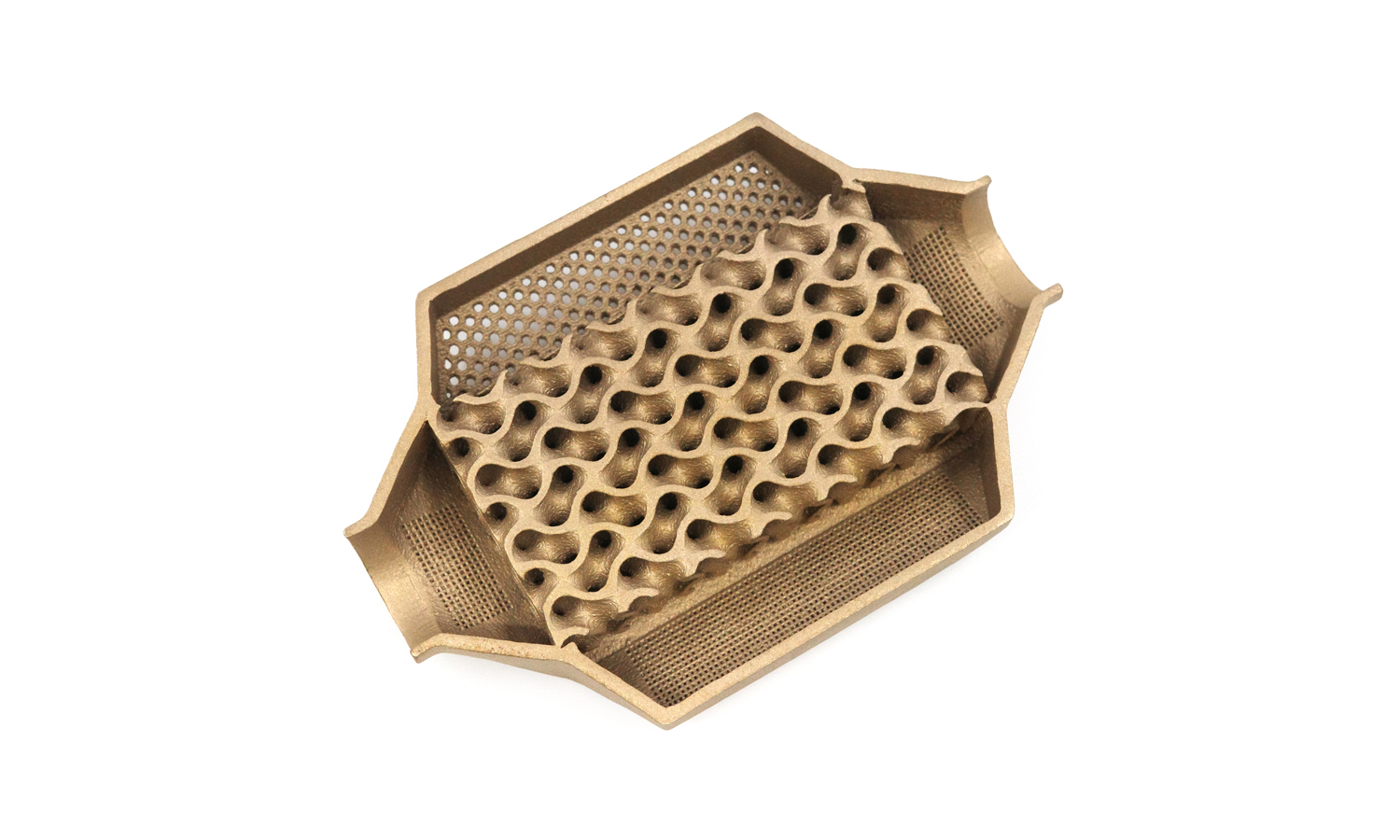
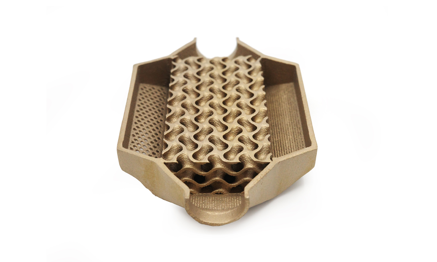
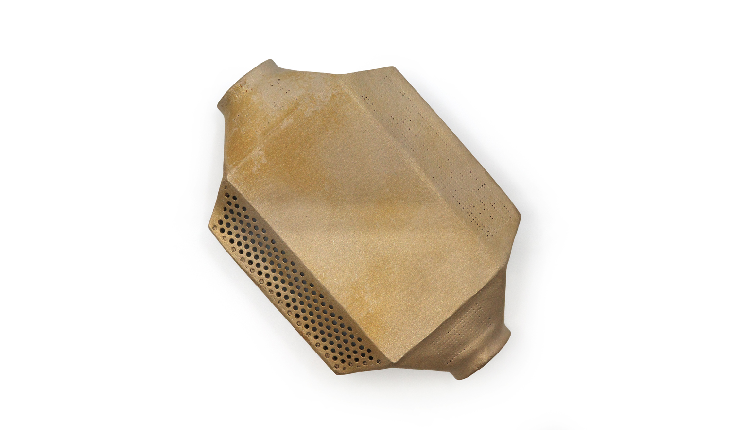
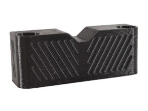
Brass 3D printing via Selective Laser Melting (SLM) offers exciting possibilities for creating intricate metal parts. This example showcases a component with a complex internal gyroid structure and perforated surfaces, demonstrating both the potential and the limitations of brass SLM.
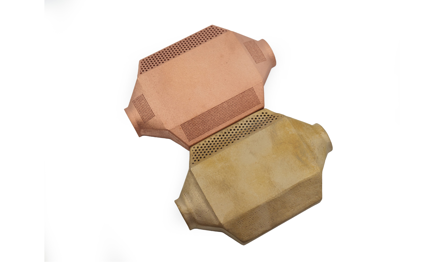
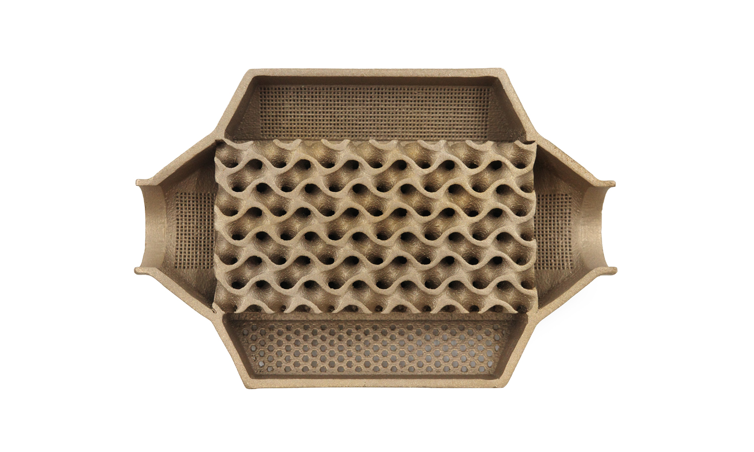
The design features a central gyroid lattice, known for its high surface area and lightweight properties, surrounded by perforated sections. While the overall shape and gyroid structure were successfully produced, the finer details of the perforations reveal the challenges of achieving high resolution in brass 3D printing.
As you can see, the 0.2mm diameter holes, intended for fine filtration or flow control, were not fully realized in the brass part. Instead of clean through-holes, they appear as indentations or partial punctures. This highlights a crucial point: brass SLM, while capable of complex geometries, may have limitations in accurately reproducing very fine details.
Minimum Detail and Design Considerations:
When designing for brass SLM, it’s essential to consider the achievable minimum feature size. While the exact limit can vary based on machine capabilities and specific brass alloys, it’s generally advisable to avoid designing features smaller than 0.4mm – 0.5mm to ensure they are properly formed.
Here are some key design tips for successful brass 3D printing:
- Generous Feature Sizing: For holes, channels, and other small features, err on the side of larger dimensions. This will increase the likelihood of successful printing and avoid issues with incomplete formation or clogging.
- Simplify Complex Details: If your design includes a high density of very small features, consider simplifying or combining them. This can improve printability without significantly compromising functionality.
- Orientation Optimization: Part orientation during printing can significantly affect feature resolution. Orienting critical features to minimize overhangs and improve support can help.
- Consider Post-Processing: If very precise dimensions or surface finishes are required for small features, factor in the need for post-processing operations such as drilling, reaming, or etching.
- Wall Thickness: Ensure sufficient wall thickness to support the structure and prevent warping or collapse during printing. Brass can be prone to distortion if thin sections are not adequately supported.
- Test Prints: For critical applications, consider performing test prints of sections containing the smallest features to validate the design and optimize printing parameters.
Brass 3D printing offers a cost-effective way to produce complex metal parts, but it’s crucial to understand its limitations. By following these design tips, you can maximize the success of your projects and achieve functional and aesthetically pleasing results.
Contact FacFox today to discuss your brass 3D printing needs and get a competitive quote!
Solution
- Step 1: A 3D model of the component was designed using CAD software.
- Step 2: The 3D model was sliced into thin cross-sectional layers.
- Step 3: Brass powder was loaded into the powder bed of the SLM machine.
- Step 4: A thin layer of powder was spread evenly across the build platform by a recoater blade or roller.
- Step 5: A high-energy laser beam was directed at the powder bed, selectively melting and fusing the brass particles according to the first cross-sectional layer of the design.
- Step 6: The build platform was lowered by a distance equal to the layer thickness.
- Step 7: Another layer of fresh powder was spread over the previously melted layer.
- Step 8: The laser beam was redirected to melt and fuse the new layer to the previous one, repeating the process for each cross-sectional layer.
- Step 9: These steps were repeated until the entire component was built.
- Step 10: After the build was complete, the component was left to cool within the powder bed.
- Step 11: The excess powder surrounding the component was carefully removed.
- Step 12: The component was detached from the build platform.
- Step 13: Support structures, if used, were removed.
- Step 14: Stress relief heat treatment was performed, if necessary, to reduce residual stresses.

