Gallery
About Project
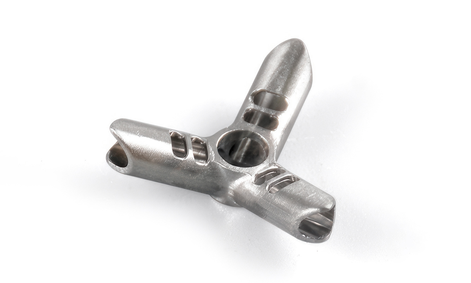
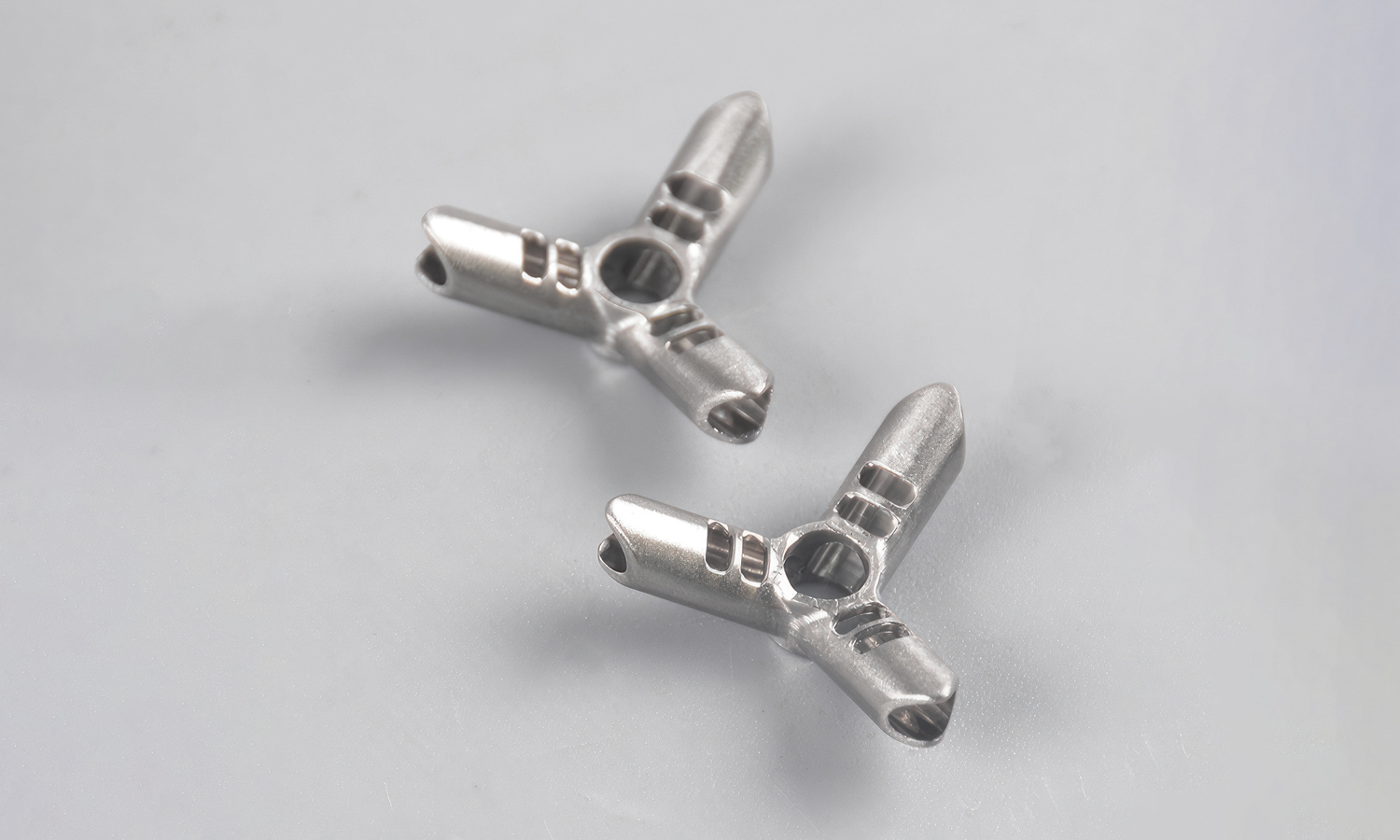
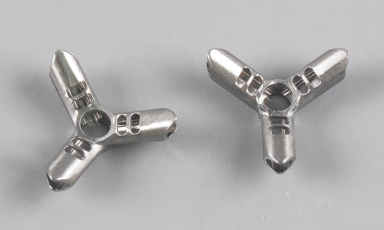
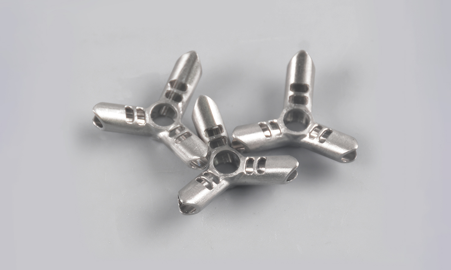
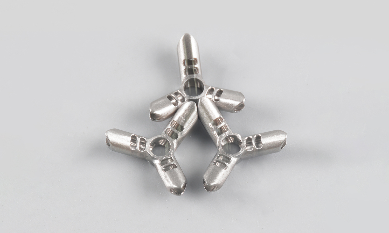
Sometimes the smallest parts do the biggest structural work. The component in the photo is a 3-way tube hub: a single node designed to connect three tubes or rods at roughly 120┬░, creating a stable, space efficient junction for modular frame systems.
Each arm acts as a hollow socket for a round tube. The open ends make assembly straightforward, while the elongated slots along the arms help reduce weight without sacrificing too much strength. Those slots can also serve practical purposes during assembly, such as visual alignment, clearance for a locking button, or space for a pin or rivet style retention. The large center opening is often used as a pass-through for a fastener, locating feature, or for reducing mass at the thickest cross-section.
YouŌĆÖll commonly find this kind of hub in lightweight structures where repeatable geometry matters: portable displays, compact racks, tent or awning frames, experimental rigs, and custom prototypes that need quick assembly and reliable alignment. Because the part combines thin-wall pockets, smooth transitions, and consistent symmetry, it rewards precise machining and careful deburring to keep tube insertion smooth and fitment consistent.
If youŌĆÖre developing connectors like this for a product, prototype, or small batch production, FacFox can help. Our CNC machining service supports complex 3D geometries, tight tolerances, and clean surface finishing across aluminum and other metals, with optional secondary processes like bead blasting, anodizing, and polishing to match both functional and aesthetic requirements.
Solution
- Step 1: The aluminum alloy billet was selected and cut to the required blank size.
- Step 2: The blank was faced and squared on a CNC mill to establish reference datums.
- Step 3: The primary locating surfaces were CNC machined to control overall geometry and alignment.
- Step 4: The central bore was drilled and then reamed or finish bored to the specified diameter and concentricity.
- Step 5: The three arm axes were indexed at 120┬░ using a rotary table or 4th axis, and each socket bore was drilled and finish machined to final size.
- Step 6: The socket openings were CNC contoured, and internal transitions were blended to improve tube insertion and stress distribution.
- Step 7: The weight reduction slots and through openings were milled, and any retention features were machined as specified.
- Step 8: All external profiles were finish milled, and edge breaks were applied to remove sharp corners.
- Step 9: The part was deburred, and internal edges were cleaned to prevent tube scratching during assembly.
- Step 10: The surface finish was produced by bead blasting or polishing, depending on the cosmetic requirement.
- Step 11: Any protective coating or anodizing was applied, if required by corrosion or appearance targets.
- Step 12: Final inspection was performed, and critical dimensions were verified with gauges or CMM before packaging.

