Gallery
About Project
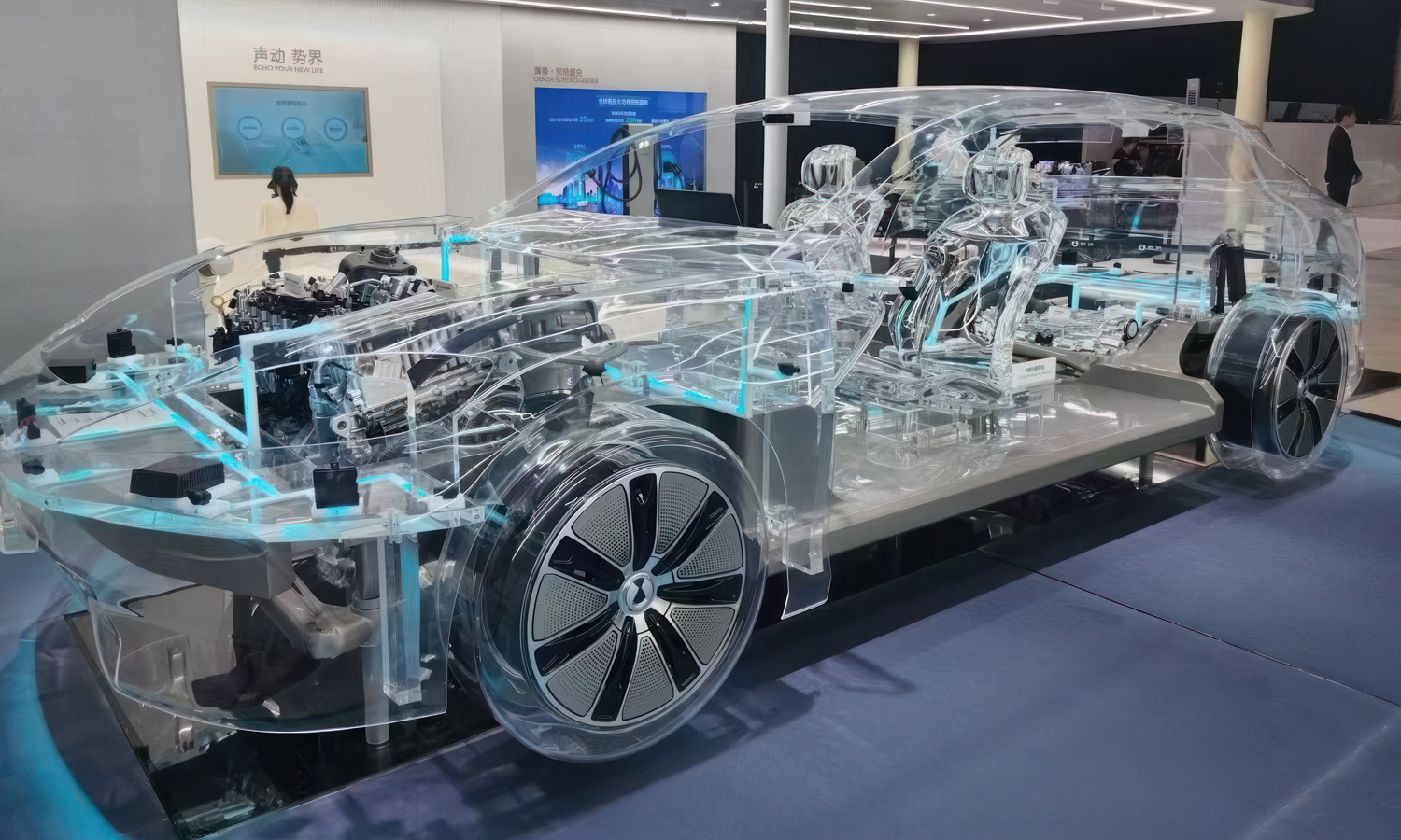
At first glance, this full-scale transparent car looks like a futuristic concept straight out of science fiction – but it’s actually a meticulously crafted display model, designed to reveal every mechanical and structural secret hidden inside a modern vehicle.
The entire outer shell, from roof to wheel arches, is made from crystal-clear material, likely high-strength acrylic or polycarbonate. This transparency isn’t just for aesthetics – it gives viewers a rare, unobstructed look at the vehicle’s chassis, wiring, suspension, and powertrain. Internal lighting strips highlight different sections, guiding the eye through the complex network of systems.
What makes this build even more impressive is the transparency of the interior structures. The seats, dashboard, center console, and many supporting frames are also made of clear material, offering a complete “X-ray” view of the vehicle’s layout. Even the wheels are enclosed in transparent housings, revealing suspension components and brake systems in full clarity.
Models like this are more than eye-catching – they are invaluable educational and marketing tools. Whether for auto shows, museums, or corporate demonstrations, they provide an unparalleled way to explain engineering principles and showcase innovation.
At FacFox, we understand the precision and craftsmanship such transparent models require. Our advanced CNC machining service can produce large-format, optically clear acrylic or polycarbonate components with tight tolerances, smooth finishes, and complex geometries – perfect for creating stunning, durable display models. Whether you’re building a full-scale vehicle mockup or a detailed product prototype, FacFox delivers the clarity and precision your vision deserves.
Solution
- Step 1: Requirements were defined and reference data were captured. Vehicle dimensions, mounting points, and exhibit constraints were documented from OEM CAD and on-site measurements. A steel/exhibit frame was specified to carry the weight of transparent parts.
- Step 2: CAD was segmented for manufacturability. The exterior shell, interior trim, seats, wheel shrouds, and system covers were split into panel-sized pieces with hidden seams, alignment tabs, and expansion gaps.
- Step 3: Materials were selected. OpticalŌĆægrade PMMA (acrylic) sheets/blocks were specified for maximum clarity, and polycarbonate was specified where higher impact resistance was needed. Thicknesses and allowable bend radii were defined for each part.
- Step 4: Forming strategy was set. Large curved body panels were planned for vacuum forming over precision molds, while thick, sculptural parts (seats, console, dash cores) were planned for 5ŌĆæaxis CNC machining from clear blocks or laminated slabs.
- Step 5: Molds and fixtures were produced. Aluminum/MDF molds and trimming jigs were CNCŌĆæmachined, sealed, and vented. Assembly fixtures were built to hold transparency-critical surfaces without imprinting.
- Step 6: Raw stock was conditioned. Acrylic blocks and sheets were ovenŌĆæannealed to relieve stress and minimize crazing during machining and bonding.
- Step 7: 5ŌĆæaxis roughing and finishing were performed. Seat shells, the dashboard core, center tunnel, and thick brackets were CNCŌĆæmilled with stepŌĆædowns appropriate for clear plastics. Small radii and tool marks were minimized by ballŌĆænose finishing passes.
- Step 8: Panels were vacuumŌĆæformed. PreŌĆædried sheets were heated to forming temperature and drawn over molds with vacuum assist. Cooling was controlled in fixtures to prevent warp and preserve optical flatness.
- Step 9: Edges and features were trimmed. CNC routers and waterjet tooling were used to trim flanges, drill fastener holes, and open light channels and inspection windows to tolerance.
- Step 10: Optical finishing was completed. Surfaces were sanded through progressive grits (Ōēł400ŌåÆ3000), buffed with plastic compounds, and then flameŌĆæpolished (PMMA) or vaporŌĆæpolished (PC) where required. Protective films were applied to handling areas.
- Step 11: Subassemblies were bonded and fastened. Solvent cements/UVŌĆæcuring adhesives were used in combination with hidden screws and threaded inserts. Assembly jigs ensured seam alignment, and expansion slots were left to accommodate thermal movement.
- Step 12: Seats and interior structures were assembled. Left/right transparent seat shells were bonded to clear bases and mounted on transparent brackets. The clear dashboard, console, and floor covers were fitted with alignment pins and fastened to the exhibit frame.
- Step 13: Lighting and wiring were integrated. LED strips, light guides, and diffusers were installed in preŌĆæmachined channels to outline systems. LowŌĆævoltage harnesses were routed through concealed passages; drivers were mounted on serviceable trays.
- Step 14: Wheels and system enclosures were completed. Transparent wheel covers and brake/suspension shrouds were turned/CNCŌĆæmilled, finished optically, and attached with quickŌĆærelease fixings for maintenance access.
- Step 15: Graphics and labels were added. Subtle laserŌĆæetching/UV printing was applied for system names and arrows, ensuring legibility without obstructing visibility.
- Step 16: Final assembly and QA were carried out. All panels were mounted to the exhibit chassis with torqueŌĆæcontrolled fasteners and vibration isolators. Clarity, fit, bond integrity, lighting, and safety were inspected; fingerprints and static dust were removed with antistatic cleaners.
- Step 17: Crating and installation were completed. Components were protected with peel films and foam cradles, packed in custom crates, transported, and reassembled onŌĆæsite using the dedicated fixtures and alignment pins.

