Gallery
About Project
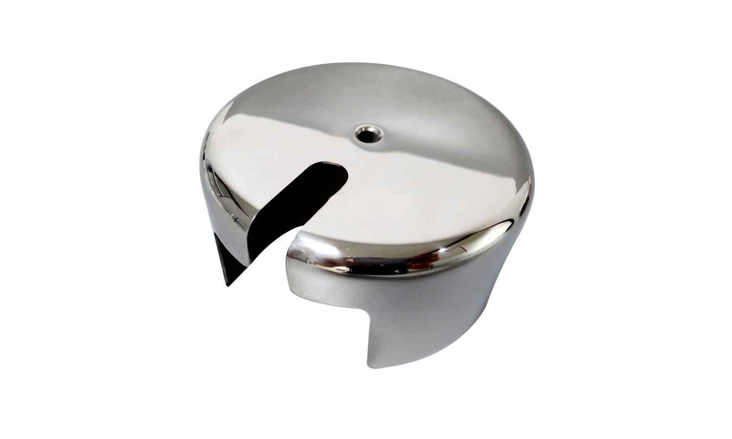
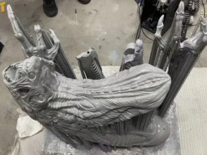
Sometimes the most ŌĆ£invisibleŌĆØ hardware ends up being the most noticeable. This polished metal piece is a light canopy cover, also called a ceiling rose. It sits at the ceiling above a pendant lamp to conceal the junction box, mounting plate, and wiring, leaving a clean, finished look that matches the fixtureŌĆÖs style.
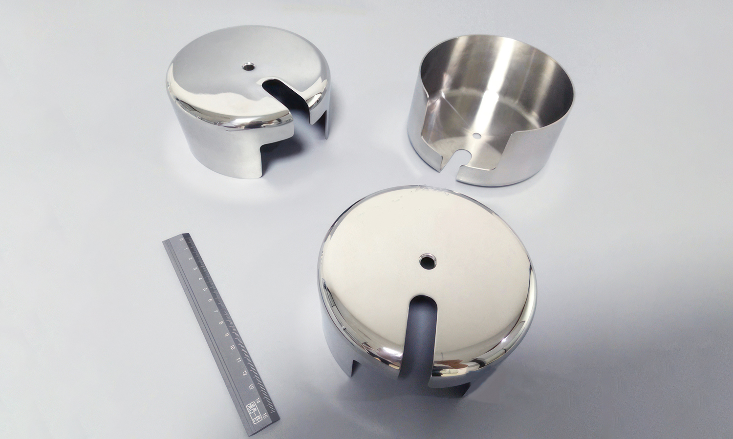
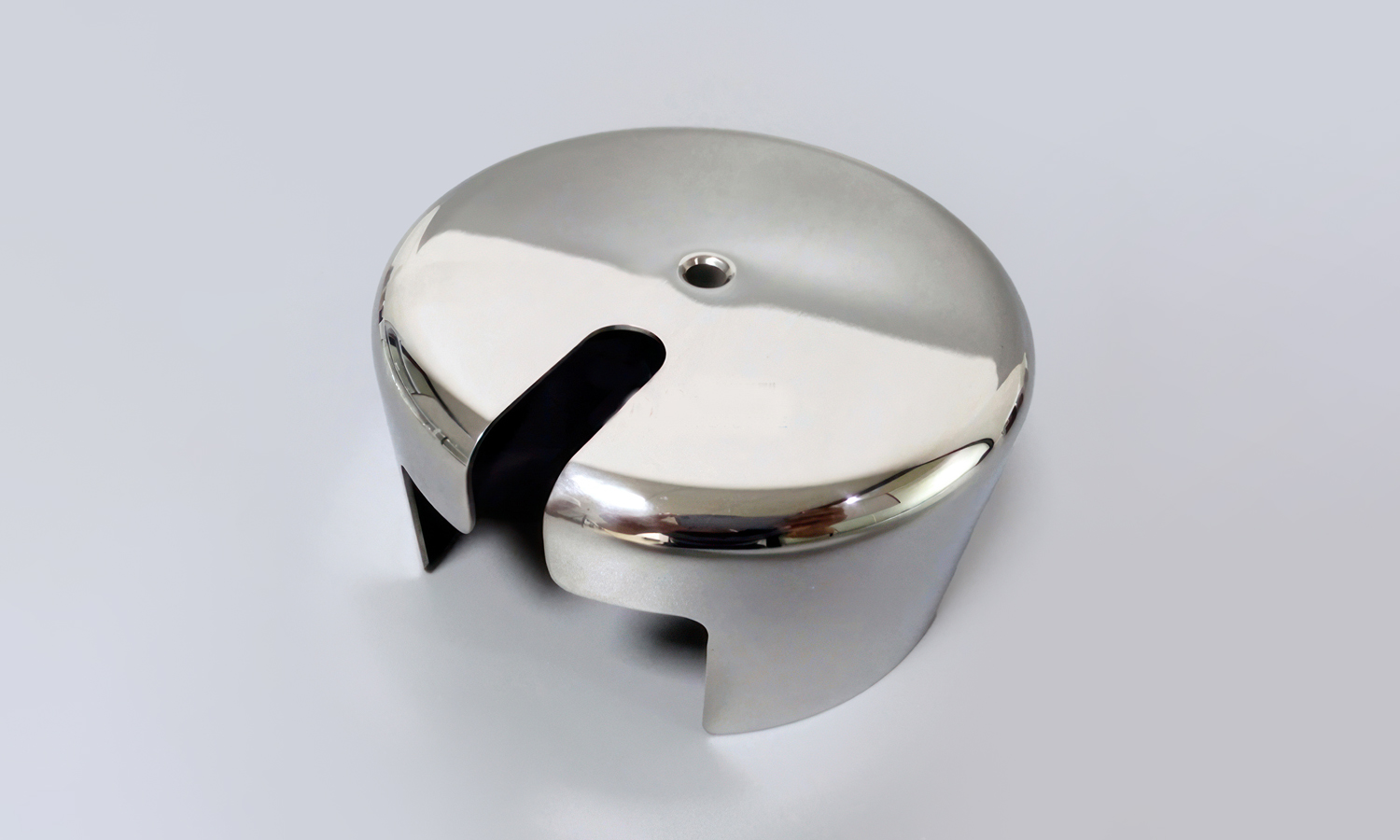
What makes this design interesting is how much function is built into a compact form. The domed top and smooth radius edges create a premium appearance while reducing sharp transitions that can show defects after finishing. The center hole is typically used for a threaded rod, cable gripper, or a fastener, depending on how the pendant is mounted. The large side opening provides cable clearance and makes installation easier, especially when routing wires without stressing the insulation. With a mirror polish, every surface matters, so consistent machining and careful finishing are essential.
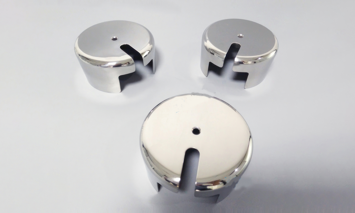
Parts like this are a great example of where CNC machining shines: tight fit, repeatable geometry, and surface quality that holds up under bright lighting and close viewing. Whether you need a prototype for a new lighting product line or stable production for a hardware refresh, the process needs to be predictable from first piece to last.
FacFoxŌĆÖs CNC machining service helps teams turn designs like this into reality with fast quoting, material options, and finishing support. From clean cosmetic surfaces to precise functional features, we can machine your parts with the consistency and detail your product deserves.
Solution
- Step 1: The 3D CAD model was reviewed, and critical dimensions for the cable opening, center hole, and internal fit were defined.
- Step 2: The raw metal billet was selected and was cut to size to provide machining allowance.
- Step 3: The billet was fixtured on a CNC lathe, and the outer diameter and top dome profile were turned to near-net shape.
- Step 4: The inner cavity was bored, and the wall thickness was controlled to meet weight and strength requirements.
- Step 5: The part was transferred to a CNC milling setup, and the side cable slot opening was milled to the specified geometry.
- Step 6: The center hole was drilled, and it was reamed or tapped as required for the fastener or cable hardware.
- Step 7: All edges were deburred, and the transitions around the slot and rim were blended to remove sharp corners.
- Step 8: The surface was prepared by sanding and mechanical polishing until the target smoothness was achieved.
- Step 9: A mirror finish was applied, and plating or clear coating was added if a higher corrosion resistance was required.
- Step 10: The part was cleaned, inspected for cosmetic defects and dimensional accuracy, and it was packaged to prevent surface scratches.


