SLA 3D Printed Autonomous Snow Blower Concept Model

SLA 3D Printed Autonomous Snow Blower Concept Model

facfox-case-study
Process 3D Print, Support Removal, Post Curing, Primer Coating, Polish, Paint
Material Resin
Quantity 1 pcs
Price Range $1-100
Lead Time 12 workdays

Gallery
About Project

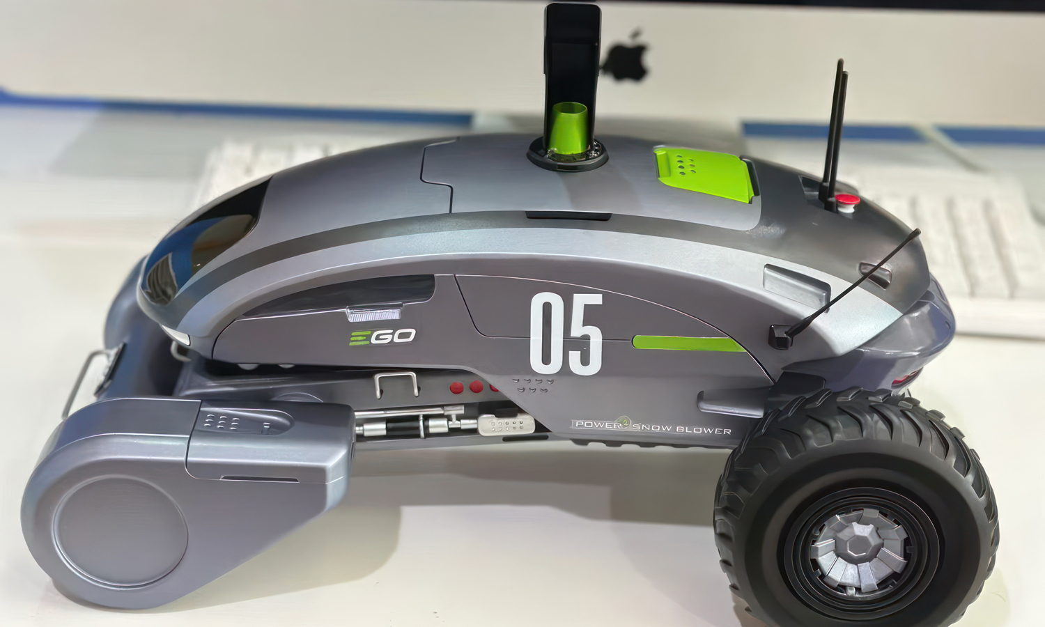
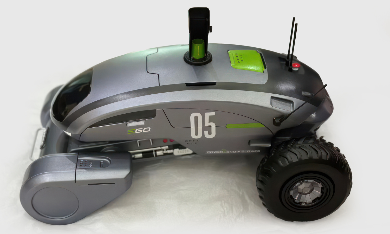
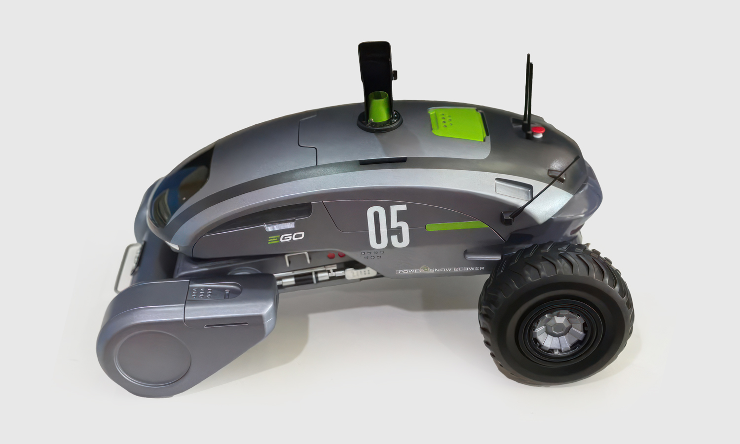
This concept model presents an autonomous snow blower robot designed for work on slippery, snow-covered ground. Its low body, large rear tires, front working module, directional chute, communication elements, and emergency control details give the prototype a convincing next-generation outdoor equipment identity.

Rather than serving as a functional machine, the prototype was created to evaluate form, proportion, color distribution, component relationships, and brand presentation before further engineering development or exhibition use.

Challenge

This industrial design prototype combines a streamlined body shell with a front snow-handling module, deep-tread wheels, a directional discharge chute, antennas, an emergency-stop button, and numerous small trim parts. The challenge was not simply to reproduce the overall shape, but to preserve clean panel gaps, consistent assembly interfaces, and crisp details across many separately manufactured components.

The finished model also required a presentation-grade surface. Metallic gray, satin gunmetal, matte black, and vivid green had to remain clearly separated, while the fine numbers, logos, and technical markings needed to follow the curved body without visible edges or distortion.
Solution

  • Step 1: Recommend a suitable process and material based on the client’s requirements and budget, assess printing and assembly risks, and discuss necessary model revisions with the client.
  • Step 2: Review the digital model as an assembly and divide the body shell, front module, wheels, chute, covers, antennas, buttons, rods, and trim into parts suited to printing, finishing, and final installation.
  • Step 3: Use SLA resin printing for the main appearance parts to reproduce smooth aerodynamic surfaces, narrow panel lines, vents, mounting details, and small industrial-design features with high precision.
  • Step 4: Reserve practical assembly clearances and locating features at joints, especially around removable covers, wheel hubs, the front attachment, and thin accessories, then trial-fit the unpainted parts.
  • Step 5: Remove supports, complete post-curing, repair support marks, and progressively sand the visible surfaces. Apply filler and primer where required to eliminate print traces and unify the substrate.
  • Step 6: Spray the components separately with satin metallic gray, gunmetal, matte black, silver, and vivid green coatings. Mask the color boundaries to preserve the sharp layered appearance of the concept design.
  • Step 7: Apply the “05” number, side lettering, logos, and technical graphics with precision decals, water-slide transfers, or pad/screen printing according to the size and curvature of each area.
  • Step 8: Assemble the painted parts with rods, antennas, tires, hubs, and small controls, correct the panel alignment, and complete a final inspection of the finish, graphics, and overall presentation.