Material Metal
Quantity 1 pcs
Price Range $1-100
Lead Time 3 workdays
Gallery
About Project
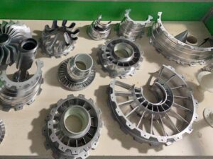
Laser-Forged. Hole-Punched. Mechanically Ready.
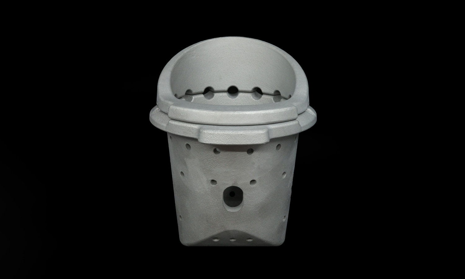
In high-performance exhaust systems, flow control isn’t just a detail-it’s a science. Enter this trio of meticulously crafted components, born from Selective Laser Melting (SLM) and sculpted from 316L stainless steel. Together, they form what we suspect is a high-end perforated exhaust diffuser assembly-but they don’t click together like Lego. They mean business, and they expect a proper fastening solution.
The Parts:
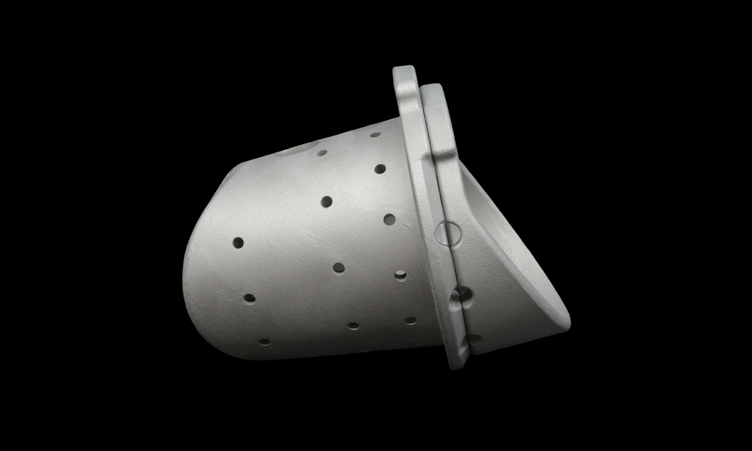
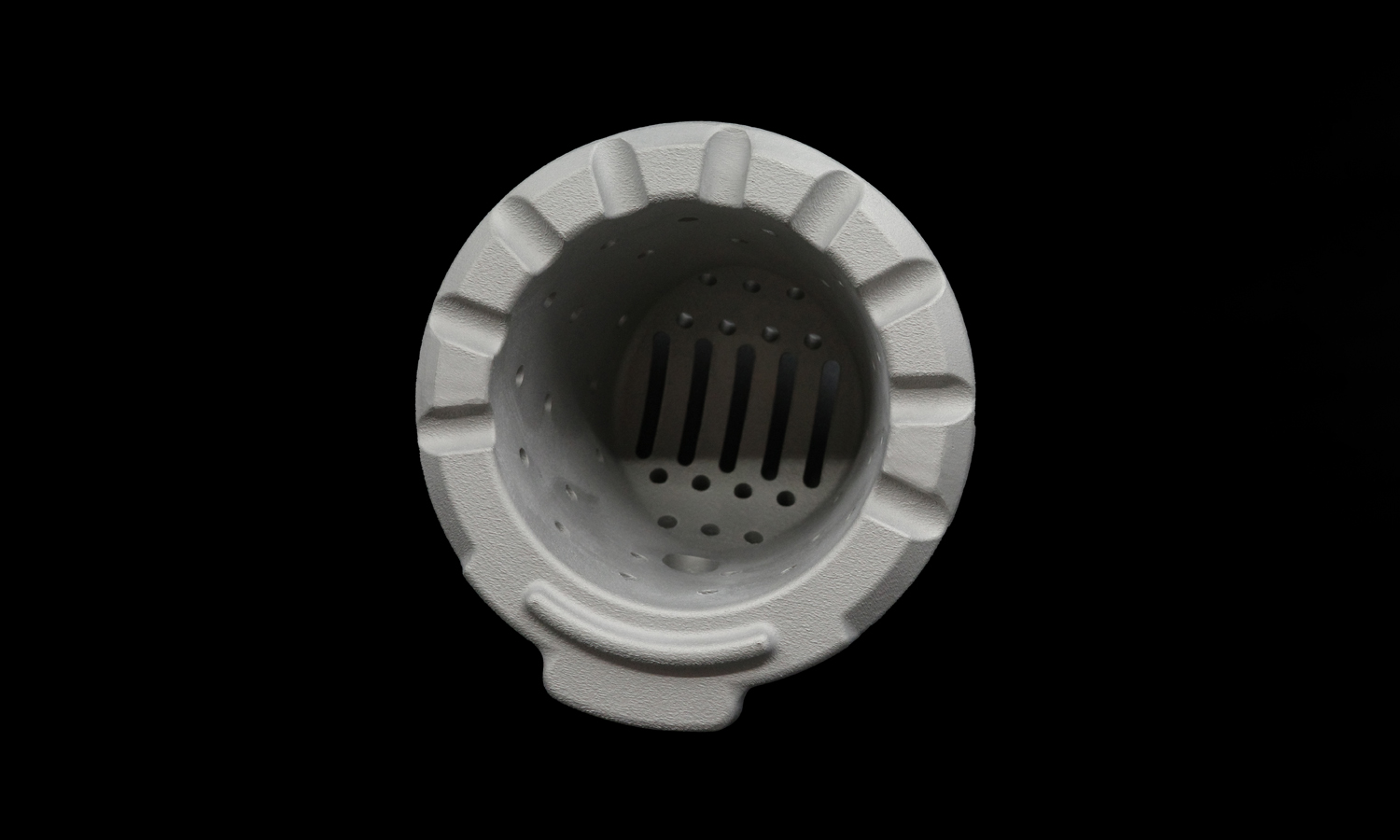
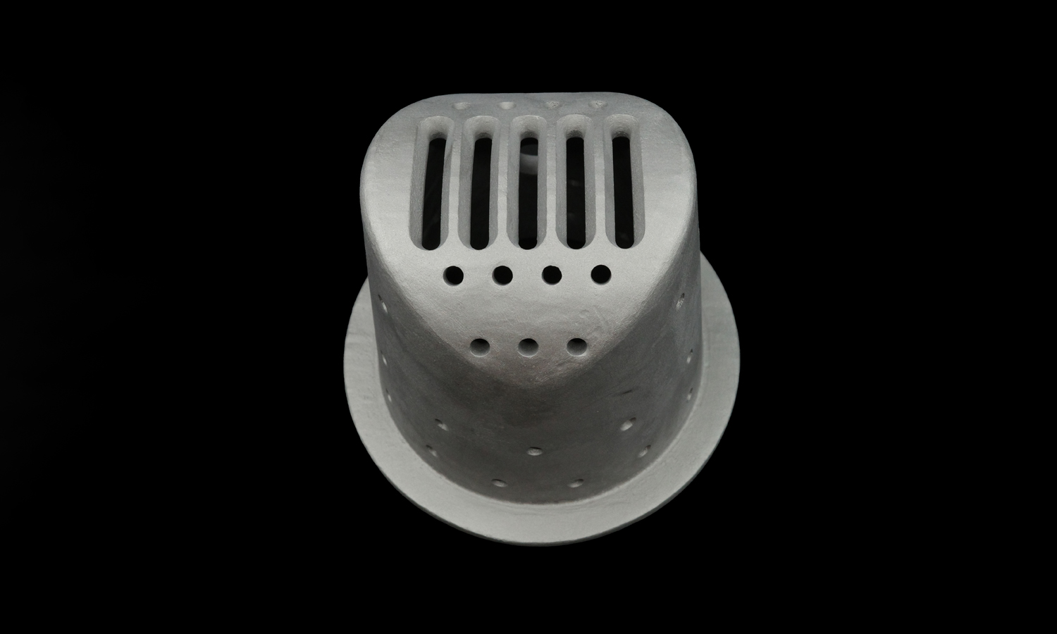
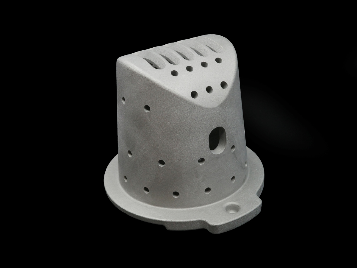
- Perforated Conical Insert. A vented, angled structure designed to shape or smooth gas flow-likely reducing turbulence, backpressure, or acoustic noise.
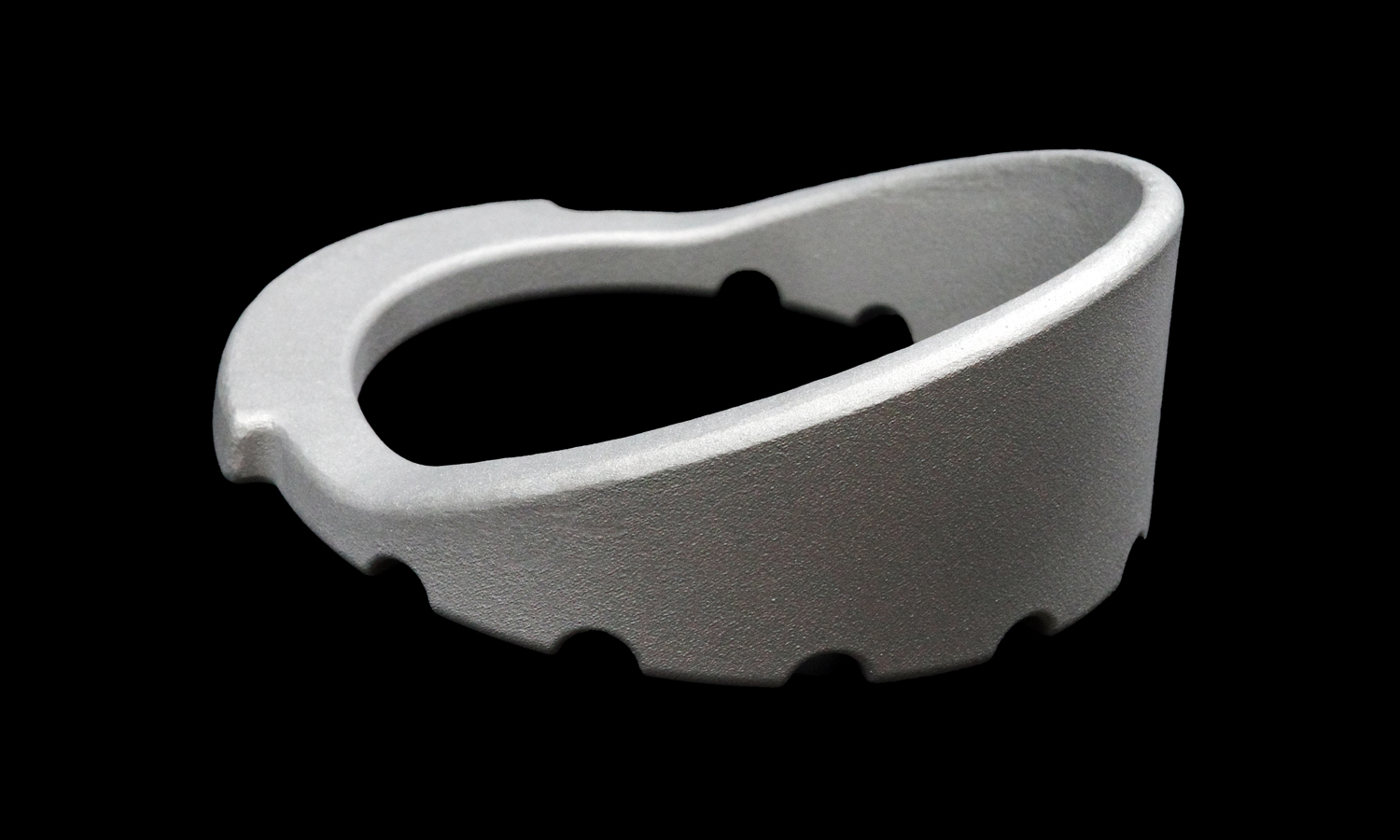
- Perforated Outer Housing. A structural shell with directional slits and surface venting, channeling exhaust while supporting the insert.
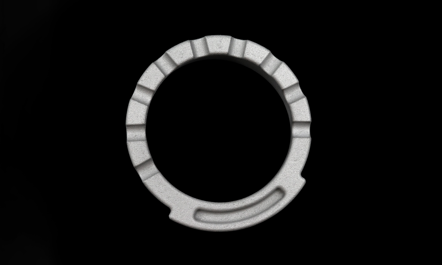
- Mounting Flange or Collar. A precision-matched ring that lines up the whole system. It doesn’t snap together-you’ll need bolts, clamps, or welds to keep this beast in place.
Notably, many of the holes along the flange edges are half-formed on each part, creating fully aligned vent holes only when assembled. That’s not an accident-it’s precision engineering for consistent flow distribution and possibly even thermal symmetry.
Functionality We Strongly Suspect:
- Pressure diffusion: Regulates turbulent gases in exhaust or thermal systems
- Heat dissipation: Maximized by surface area and venting
- Acoustic moderation: Those perforations aren’t just pretty-they may tame vibrations and reduce noise
- Modular maintenance: With tool-fastened assembly, you can disassemble, inspect, or swap components with ease
And yes-the surface finish is unapologetically raw. That’s the beauty of SLM: no coatings, no post-polish fluff, just functional metal where it matters.
Powered by FacFox SLM Metal 3D Printing
At FacFox, we specialize in producing parts that traditional manufacturing would charge triple just to frown at. Our SLM 3D printing service gives engineers the freedom to design with zero concern for tool paths or parting lines.
With us, you get:
- Functional metals like 316L, Inconel 625, Ti64, AlSi10Mg
- High-complexity parts with fine internal features
- Support for mechanical fastening, post-machining, and surface treatments
Ready to turn your complex models into working metal?
Team up with FacFox-where your boldest ideas go from powder to power.
Solution
- Step 1: Design Preparation. The 3D models of all components were finalized in CAD software. Design features such as perforation patterns, flange dimensions, and wall thicknesses were carefully validated for printability and structural integrity. The files were then exported as STL and oriented in the build space for optimal support and thermal stress distribution.
- Step 2: Powder Layering. 316L stainless steel powder was evenly spread onto the build platform using a recoater blade. A uniform layer thickness, typically between 20ŌĆō40 microns, was maintained throughout the build.
- Step 3: Selective Laser Melting. Each cross-sectional layer of the part geometry was selectively melted using a high-powered fiber laser. The laser scanned the surface based on the sliced design data, fully melting the powder in designated areas and bonding it to the layer below.
- Step 4: Layer-by-Layer Construction. The build platform was lowered incrementally, and fresh layers of powder were applied and melted in sequence. This additive process was repeated layer by layer until all parts were fully printed in solid 316L stainless steel.
- Step 5: Post-Build Cooling. After the final layer was fused, the entire build chamber was allowed to cool gradually under an inert gas environment to minimize residual thermal stresses and prevent oxidation.
- Step 6: Powder Removal. The finished parts were extracted from the powder bed. Loose, unfused powder was removed using compressed air, brushing, and vacuum systems. The reclaimed powder was sieved and reused when possible.
- Step 7: Heat Treatment / Sintering. To relieve internal stresses and improve mechanical properties, the printed parts were subjected to a sintering or stress-relief annealing process. They were heated in a vacuum or inert atmosphere furnace at temperatures ranging from 900┬░C to 1100┬░C, depending on final property requirements.
- Step 8: Support Removal & Surface Cleaning. Support structures, if used, were removed manually or via CNC post-machining. The surfaces were then grit-blasted or bead-blasted to remove oxide layers and achieve a uniform matte finish.
- Step 9: Dimensional Inspection. Each component was inspected using calipers, CMMs, and visual checks to ensure tolerances, perforation placement, and flange features met design specifications.
- Step 10: Assembly Preparation. Finally, the components were matched and aligned to confirm that bolt holes, flange surfaces, and mating features could be fastened together with external tools. At this stage, secondary machining or fitting adjustments were performed if required.


