Material Metal
Quantity 1 pcs
Price Range $1-100
Lead Time 2 workdays
Gallery
About Project
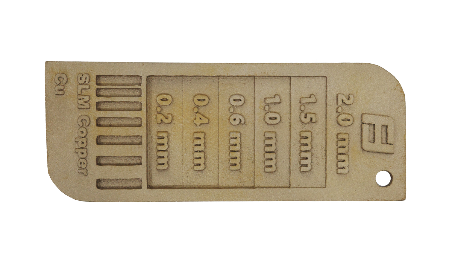
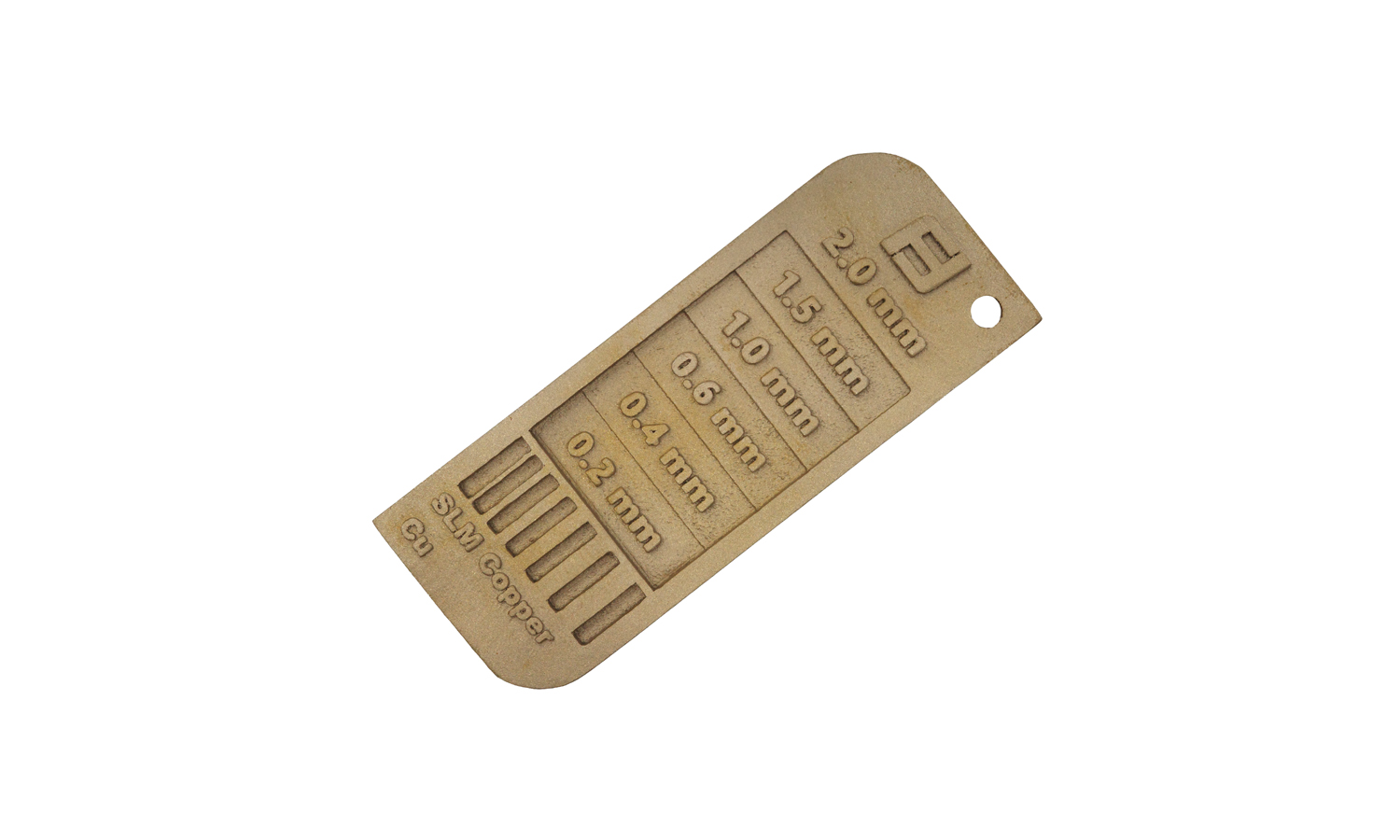
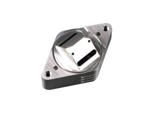
This SLM (Selective Laser Melting) 3D printed brass wall thickness tester showcases the capabilities and limitations of metal 3D printing. The part was designed to test the minimum wall thickness achievable with the SLM process.
While the tester successfully printed all the intended thicknesses (0.2mm, 0.4mm, 0.6mm, 1.0mm, 1.5mm, and 2.0mm), there are some observations to note:
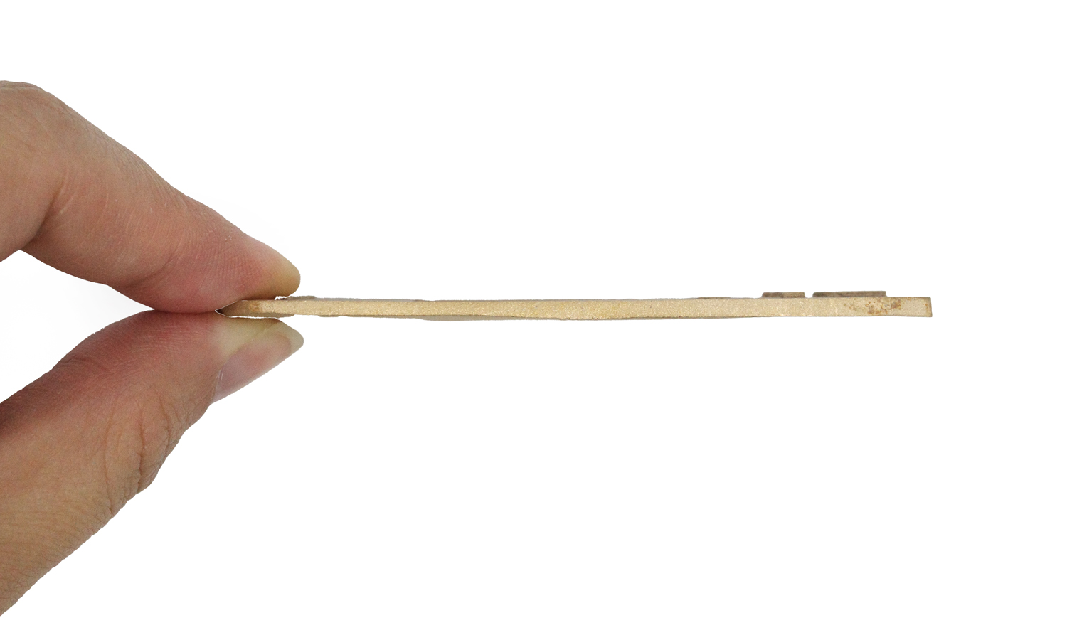
- The 0.2mm and 0.4mm sections are quite thin, resulting in some curving along the lower part of the sample. For optimal results and to maintain straightness, a minimum thickness of 0.6mm or greater is recommended.
- There are some remaining support marks on the raised letters. These marks are a common artifact of metal 3D printing, as support structures are often required to ensure successful printing.
- The sharp corners of the sunken slots were printed with a slight roundness. This is a limitation of metal 3D printing, which may not be able to reproduce the same level of fine detail as resin-based 3D printing processes.
FacFox 3D Printing Service
Looking for reliable and high-quality 3D printing services? FacFox offers a wide range of 3D printing technologies and materials, including SLM for metal parts. Whether you need prototypes, functional parts, or end-use products, FacFox can meet your needs with precision and efficiency. Visit FacFox today to learn more about their 3D printing capabilities and get a quote for your project.
Solution
- Step 1: A thin layer of metal powder was spread onto the build platform.
- Step 2: A high-powered laser beam was selectively directed to melt and fuse the powder particles according to the cross-section of the design.
- Step 3: The melted material was solidified, forming a solid layer of the part.
- Step 4: The build platform was then lowered by a small increment.
- Step 5: A new layer of metal powder was spread over the solidified layer.
- Step 6: Steps 2-5 were repeated layer by layer until the entire part was completed.
- Step 7: The finished part was removed from the build chamber, and excess, unfused powder was extracted.
- Step 8: Any necessary support structures, which were also printed, were carefully removed.
- Step 9: The part was then post-processed, which might include surface finishing or heat treatment.


