Gallery
About Project
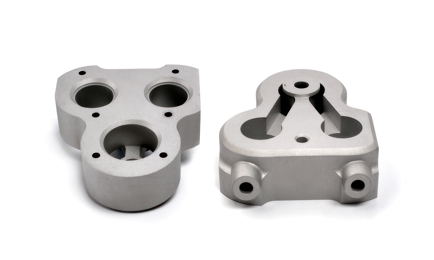
Feast your eyes on this intricately designed component, a testament to the precision and versatility of CNC machining. Crafted from robust aluminum alloy, this part showcases the complex geometries and tight tolerances achievable through computer-controlled manufacturing.
As you can see from the various angles, this piece features multiple precisely machined holes, both through and counterbored, suggesting secure and accurate mounting within a larger assembly. The presence of internal ribs and carefully sculpted cavities hints at its functional role, likely within a motor transmission system.
The robust construction and the choice of lightweight yet strong aluminum alloy make it an ideal candidate for demanding applications where durability and performance are paramount. Whether it’s a mounting bracket, a housing component, or an integral part of the power transmission mechanism connected to a motor, the accuracy afforded by CNC machining ensures seamless integration and optimal functionality. The consistent surface finish and sharp, clean edges are hallmarks of a subtractive manufacturing process that guarantees high-quality results.
Looking for precision-engineered metal parts for your motor, transmission, or other demanding applications? At FacFox, we offer cutting-edge CNC machining services, specializing in aluminum alloys and a wide range of other materials. Our expert team and advanced machinery are equipped to handle complex designs with tight tolerances, delivering high-quality prototypes and production parts with speed and efficiency. Contact FacFox today to bring your designs to life and experience the power of precision manufacturing!
Solution
- Step 1: The initial design for the component was created using CAD (Computer-Aided Design) software.
- Step 2: Based on the CAD model, precise machining instructions in the form of CNC (Computer Numerical Control) code were generated using CAM (Computer-Aided Manufacturing) software.
- Step 3: A billet or block of aluminum alloy was selected as the raw material for the part.
- Step 4: The aluminum billet was securely fixtured onto the worktable of a CNC machining center.
- Step 5: Various cutting tools were automatically selected and loaded into the spindle of the CNC machine.
- Step 6: Material was progressively removed from the aluminum billet by the rotating cutting tools, following the programmed toolpaths generated in the CAM software. This process was repeated with different tools to achieve the desired external shape and internal features.
- Step 7: The larger central bore and other significant openings were machined using appropriate drilling or boring tools.
- Step 8: The smaller mounting holes were drilled at precise locations according to the design specifications.
- Step 9: Counterbores or countersinks for fasteners were created using specialized cutting tools.
- Step 10: Any internal features, such as the visible ribs and cavities, were machined using end mills or other suitable tools.
- Step 11: Throughout the machining process, the dimensions and tolerances of the part were continuously monitored using precision measuring instruments, either manually or through automated probing systems.
- Step 12: Once all machining operations were completed, the finished component was removed from the CNC machine.
- Step 13: The part was likely subjected to deburring and cleaning processes to remove any sharp edges or machining residue.
- Step 14: Finally, the component may have undergone surface finishing treatments, such as anodizing, depending on the application requirements.

