Gallery
About Project
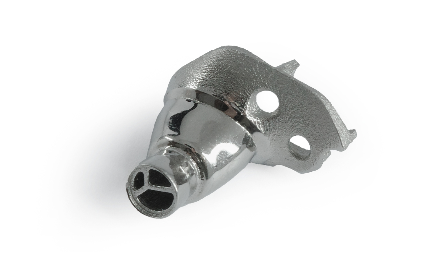
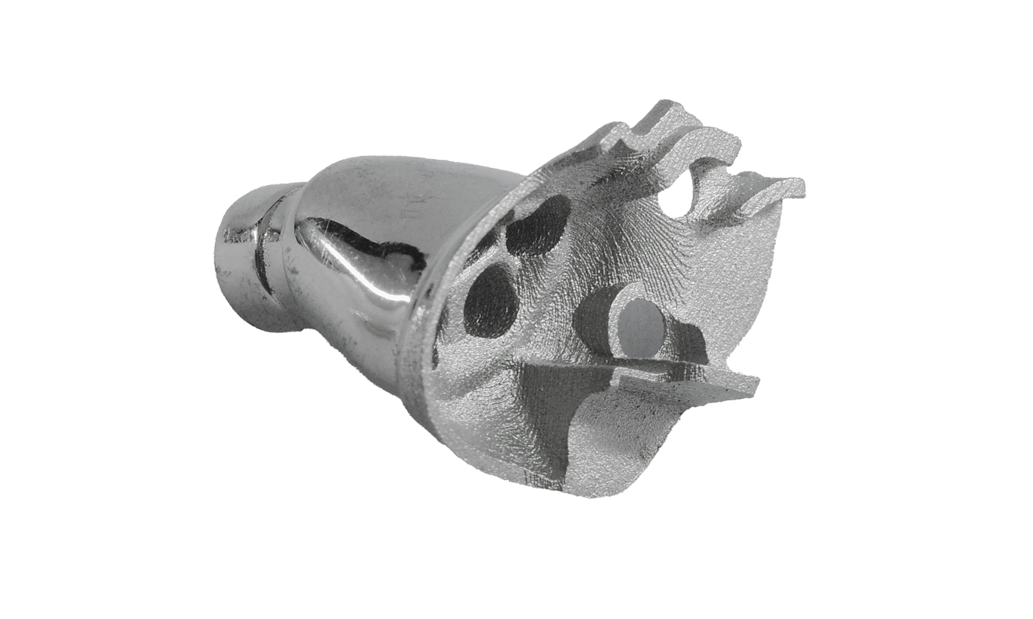
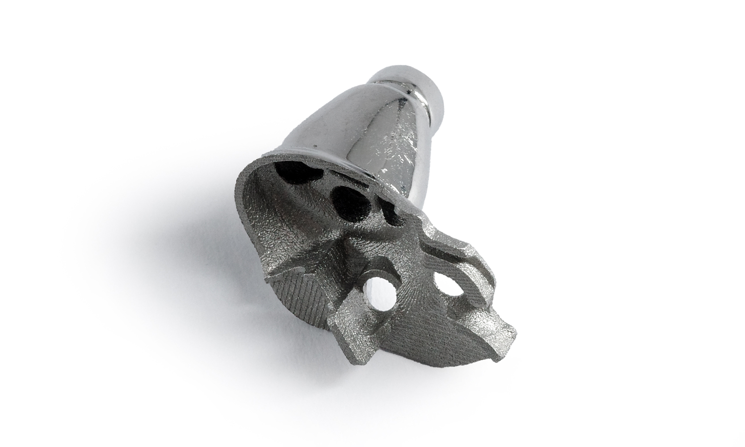
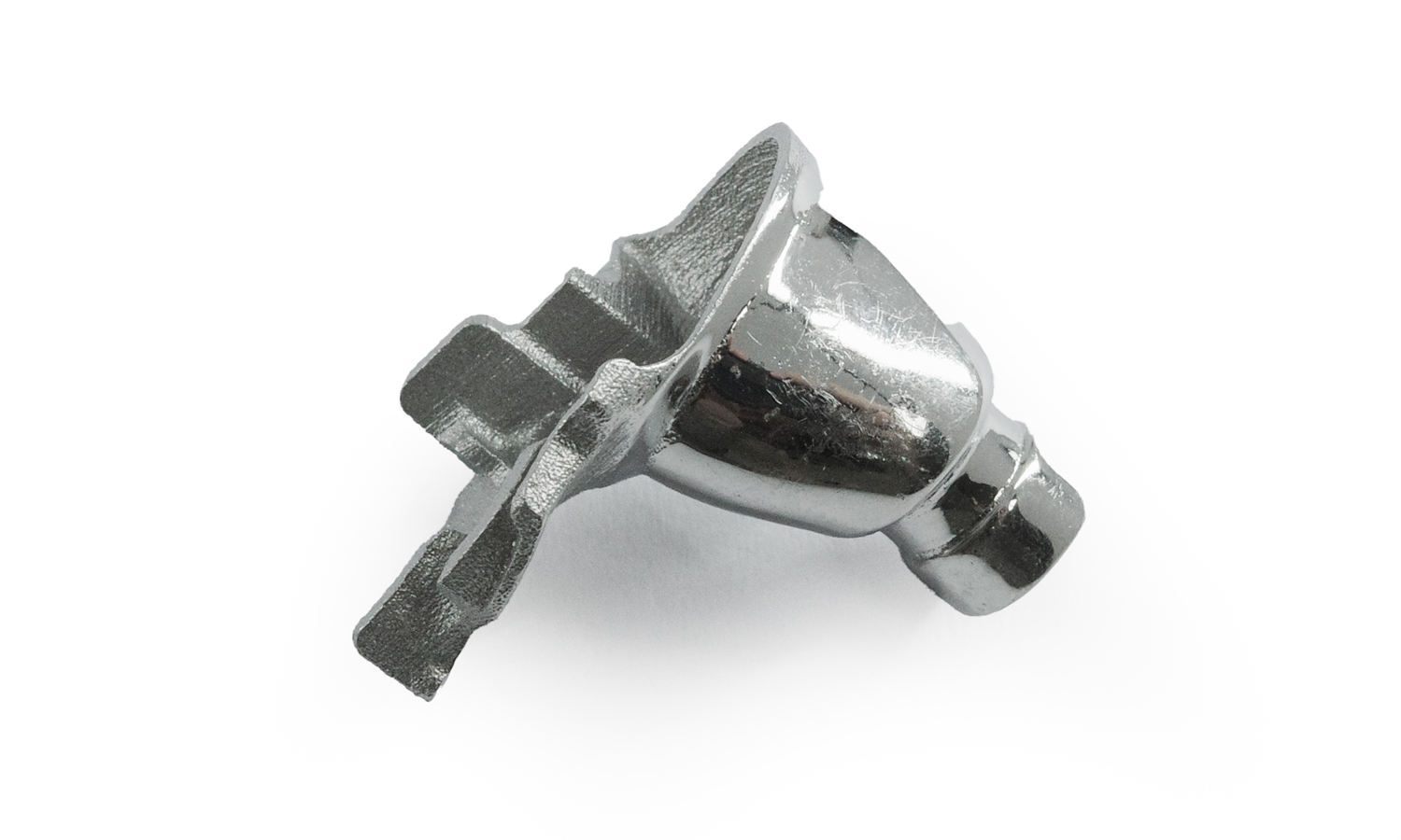
Metal 3D printing is revolutionizing electronics prototyping, enabling the creation of complex components with unmatched precision. This BinderJet 3D printed SS316L wireless earbud bottom housing is a testament to this technological advancement.
Its distinctive conical shape, tapering to a smaller cylindrical end, is a common design feature in earbud components, often linked to acoustic delivery systems. The component’s intricate details, including the three-way opening and mounting holes, are executed with remarkable accuracy.
SS316L stainless steel, known for its corrosion resistance and biocompatibility, is an ideal choice for wearable electronics. The polished metal finish not only enhances the component’s aesthetic appeal but also potentially improves its acoustic properties.
FacFox: Your Partner in Metal 3D Printing
FacFox is at the forefront of metal 3D printing technology. We specialize in providing high-quality, cost-effective, and rapid metal 3D printing services for electronics prototyping. Our state-of-the-art equipment and experienced engineers ensure that your designs are brought to life with precision and efficiency.
By choosing FacFox, you can:
- Accelerate product development: Benefit from our rapid turnaround times.
- Realize complex designs: Leverage our advanced 3D printing capabilities.
- Select from a wide range of metal materials: Tailor your components to specific requirements.
- Ensure exceptional quality: Rely on our rigorous quality control processes.
Experience the Future of Electronics Prototyping
Contact FacFox today to learn more about our metal 3D printing services and how we can help you bring your innovative ideas to life.
Solution
- Step 1: 3D Model Creation. A detailed 3D model of the earbud bottom housing was designed using computer-aided design (CAD) software.
- Step 2: Slice Preparation. The 3D model was sliced into thin layers, each representing a cross-section of the final component.
- Step 3: Powder Bed Preparation. A thin layer of stainless steel powder was spread evenly across the build plate.
- Step 4: Binder Jetting. A binder solution was selectively jetted onto the powder bed, binding the particles together to form the desired shape of the first layer.
- Step 5: Powder Recoating. A new layer of powder was spread over the partially built component.
- Step 6: Layer-by-Layer Build-up. Steps 4 and 5 were repeated, layer by layer, until the entire component was built.
- Step 7: Debinding. The built component was subjected to a debinding process to remove the binder material, leaving behind a solid metal structure.
- Step 8: Sintering. The component was sintered in a high-temperature furnace to fuse the metal particles together, resulting in a dense and strong final product.
- Step 9: Post-Processing. The sintered component was post-processed to achieve the desired surface finish and dimensional accuracy, which may include machining, grinding, or polishing.
- Step 10: Quality Inspection. The finished component was inspected to ensure it met the specified quality standards.
