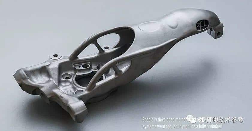
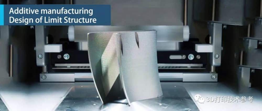
Structural optimization design has become an important tool for structural innovation design, which can be divided into size optimization, shape optimization, and topology optimization. The results of structural optimization are sometimes more complicated, and it is difficult or impossible to prepare using traditional manufacturing processes. The processing method of additive manufacturing technology greatly liberates the design freedom and makes up for the shortcomings of traditional manufacturing methods. It is promising to integrate structural optimization with additive manufacturing and develop innovative design technologies for additive manufacturing.
However, additive manufacturing is not “free” manufacturing, and the forming ability of the equipment is affected by many factors. Taking SLM as an example, the layered constraint has a great influence on the accuracy of the surface. The laser deep penetration constraint will affect the formation of the pendant surface structure, and the light spot constraint limits the resolution of the formed part. Finding and describing additive manufacturing constraints and integrating into the structural optimization process to form a high-quality configuration design method that considers manufacturability has become the key to achieving the integration of additive manufacturing and structural optimization. In this issue, we use the research results of the South China University of Technology and other teams to show the types of structural constraints of additive manufacturing and discuss their limit-size designs.
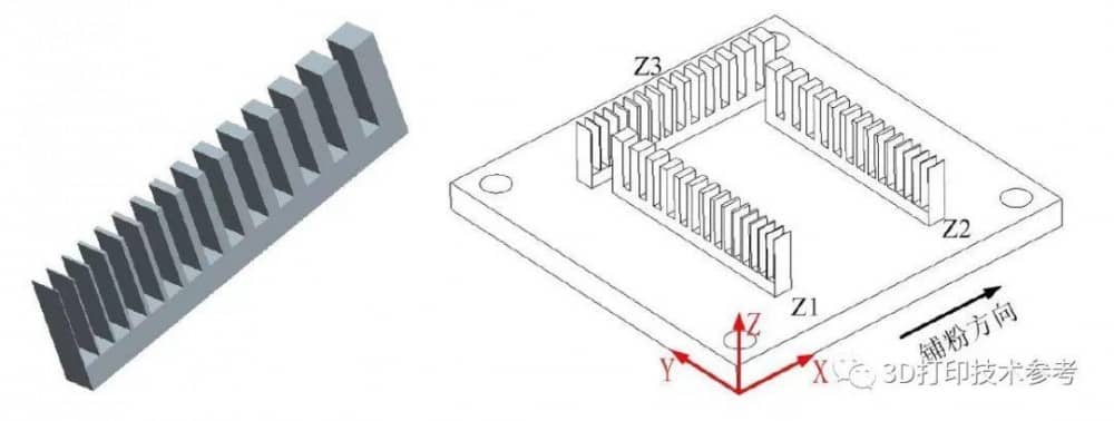
▌Thin-walled features
There is a minimum size limit for thin-walled features. Due to laser spot errors, it is not possible to form thin-walled parts that are smaller than the spot size. Even if thin walls are too small, they cannot be applied to actual mechanical parts. Studies have shown that the minimum wall thickness of thin walls should be greater than 0.3mm, and the smaller the size, the greater the error.
▌Pointed corner features
The sharp corner feature has a minimum size limitation, which is mainly constrained by the laser spot. At the sharp corner, due to the interference of the spot, the shape and size of the sharp corner will cause large errors. Generally speaking, a too-small angle is not suitable for SLM processing.
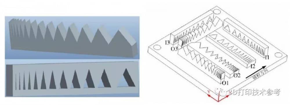
Studies have shown that the vertical placement of the outer sharp angle is too large, and the shape accuracy is low, and it should be avoided as much as possible; and sharp angles less than 8 ° should not be formed by SLM. The horizontal placement accuracy of the inner sharp corner is high; the vertical placement size is too large, and the shape accuracy is low, and it should be avoided as much as possible; and sharp angles less than 8 ° should not be formed by SLM.
▌Square hole feature
The vertical hole size and shape accuracy are generally high, and the minimum feature size is mainly constrained by the laser spot; the horizontal hole is affected by the laser spot and the laser deep penetration, there are the minimum and maximum size restrictions, and the shape and accuracy are often problematic.
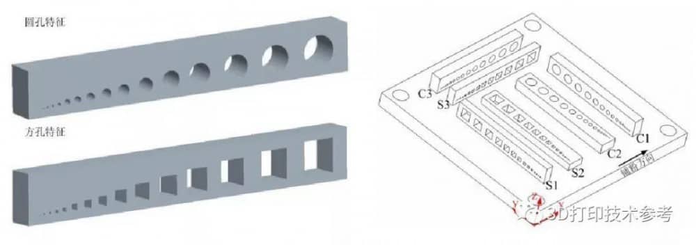
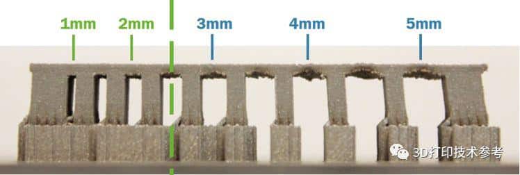
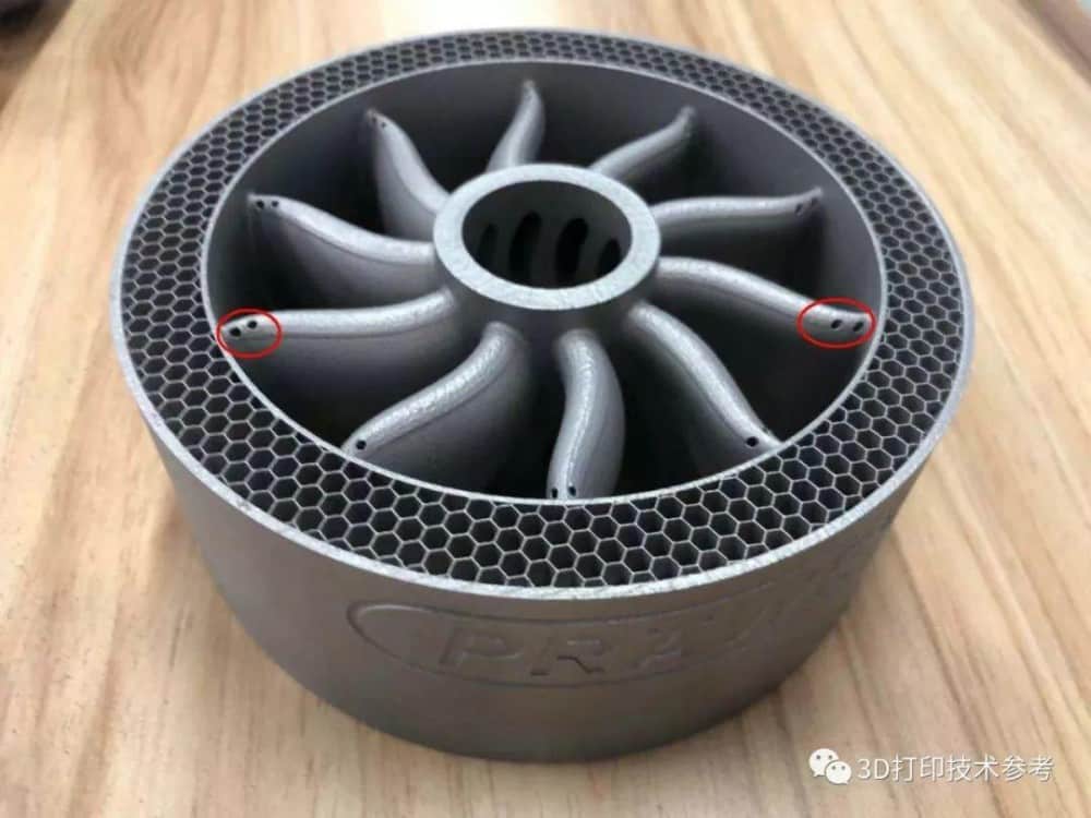
Studies have shown that the diameter of the horizontal circular hole should be greater than 0.4mm, but the horizontal circular hole is often accompanied by slag on the top, which affects the roundness; the minimum diameter of the vertical circular hole should be greater than 0.3mm. The span of the horizontal square hole should be between 0.5-1.5mm, and the side length of the vertical square hole should be greater than 0.3mm. The use of round holes is mostly seen in conformal cooling channels.
▌Cylinder / square column features
The column features are affected by the delamination and laser spot. There are limitations on the minimum size and aspect ratio, and the placement angle and method have a greater impact on the molding.
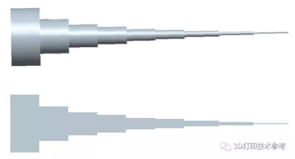
The smaller the size of the column, the greater the size error. Whether the cylinder or square column, the design size is less than 0.5mm, it is not suitable to use SLM molding. Its characteristic size can provide a reference for the design of the lattice structure.
▌Spherical features
The characteristics of the sphere are limited by the minimum and maximum dimensions of the laser spot, deep laser penetration and layering constraints. Regardless of the molding strategy, the sphere is affected by the laser deep penetration effect, and the accuracy of the sphere will also be affected to a certain extent.
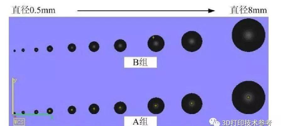
When the ball diameter is less than 2mm, the lower half of the sphere is bonded to the substrate, and the shape accuracy is low; if the ball diameter is greater than 8mm, a large amount of support needs to be added to the lower part, and the accuracy is poor.
▌High aspect ratio features
High aspect ratio features have a maximum size limit. Too large an aspect ratio makes it difficult to meet the actual strength of the part, and is also limited by the molding range of the equipment. In fact, it has the most significant influence on thin walls, cylinders, square columns, etc. under the limit size, and the forming height of the smallest feature will be limited by factors such as stress in the forming process. The analysis of this aspect has been uploaded to the QQ group.
▌Draping constraint
Suspension structures whose angle between the surface and the horizontal direction is lower than the critical value require supporting materials. This critical value is usually 45 °. According to the manufacturing principle of raw materials and the raw materials used, it can be seen that when processing the overhanging part, the lower layer is made of powder and other materials, which cannot provide sufficient support force and heat transfer path, and the structure is prone to collapse or warpage. Although adding a support structure can solve these problems, it means additional material loss, increased forming time, and increased post-processing work, and may also affect the internal stress distribution of the part.
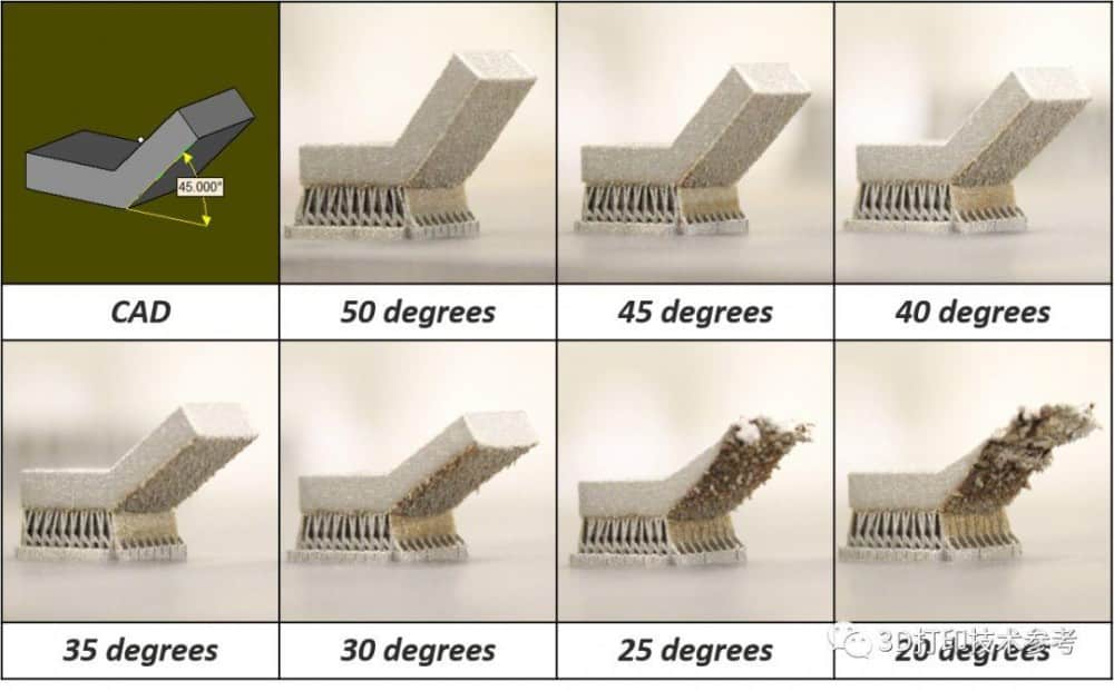
In fact, the size of the self-supporting angle will be different depending on the printing materials. Titanium alloys can have a self-supporting angle of 40 to 45 degrees, while steel, cobalt-chromium alloys, and aluminum alloys may be between 50 and 55 degrees.
▌Closed cavity constraint
If there is a closed cavity in the part, the material used for support in the cavity cannot be cleaned out after printing. For metal powder forming, etc., after the printing is completed, the powder in the cavity cannot be cleaned out, so the additive manufacturing should avoid the structure with a closed cavity as much as possible.
▌Gap feature
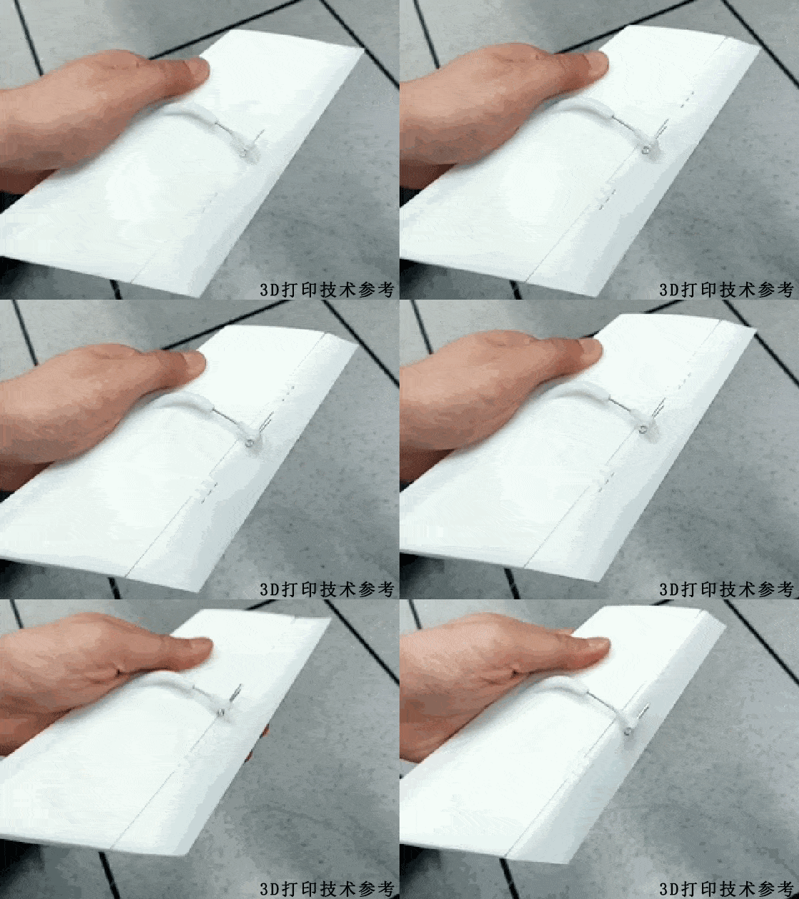
The gap feature faces a direct-printing assembly-free structure, which is constrained by laser spot, laser penetration, and layering. The gap feature has a minimum size limit, and the shape of the gap feature has a great influence on its formability. The size of the gap feature determines whether the assembly-free structure has motion properties. For example, the overall active structure that we introduced in “Sparrow H” encountered design problems of the gap feature during the design and manufacturing process. This is a special topic, which is difficult to discuss in this article.
Impact Analysis
The minimum structure manufactured by SLM will be affected by the spot size, printing process, materials, and optical system.
The spot constraint is mainly reflected in the width of the melt channel. From the geometric relationship, the width of the melt channel determines the minimum size that the SLM can form.
For the process, you need to see how advanced it is. Sometimes the limit constraints are followed in the design, but through the adjustment of the process, you can actually achieve a smaller size than the limit feature. For example, for a thin wall of 0.1mm, if the scanning distance is 0.08mm, some devices will scan two lines, and the thickness of the thin wall will naturally increase; some devices will set the minimum fill identification value, facing the case of a thickness of 0.1mm, The light spot may only scan the outline. For the slag that may appear in the round hole structure and the square hole feature, advanced technology may have achieved a completely unsupported smooth molding, such as the SLM unsupported process we mentioned earlier.
The influence of materials is also very significant. The molding characteristics of each material are not the same. Some may be easy to mold, and the details will be very expressive, and the feature size can be smaller. While some materials may have a relatively high viscosity, the expressiveness of details may be worse.
In short, there is a reference value for the limit structure whether it is for designers or craftsmen.

