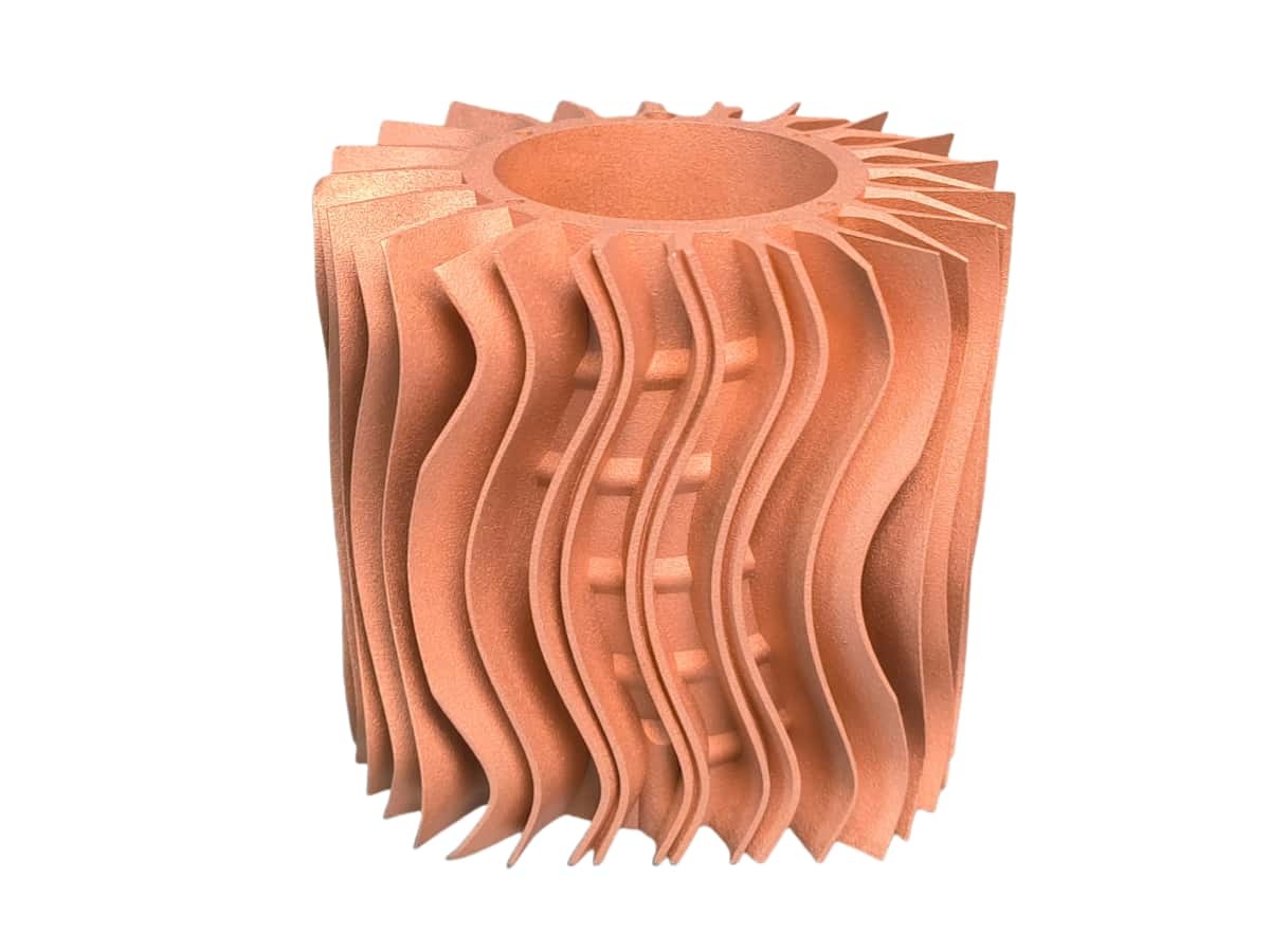
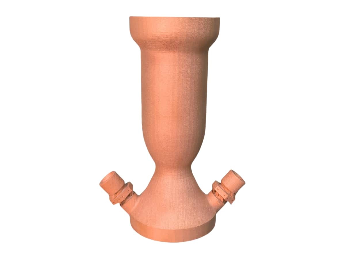
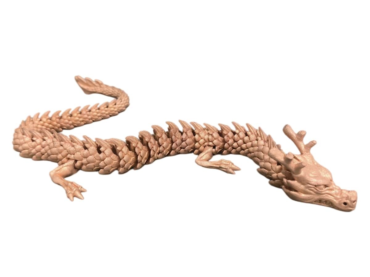
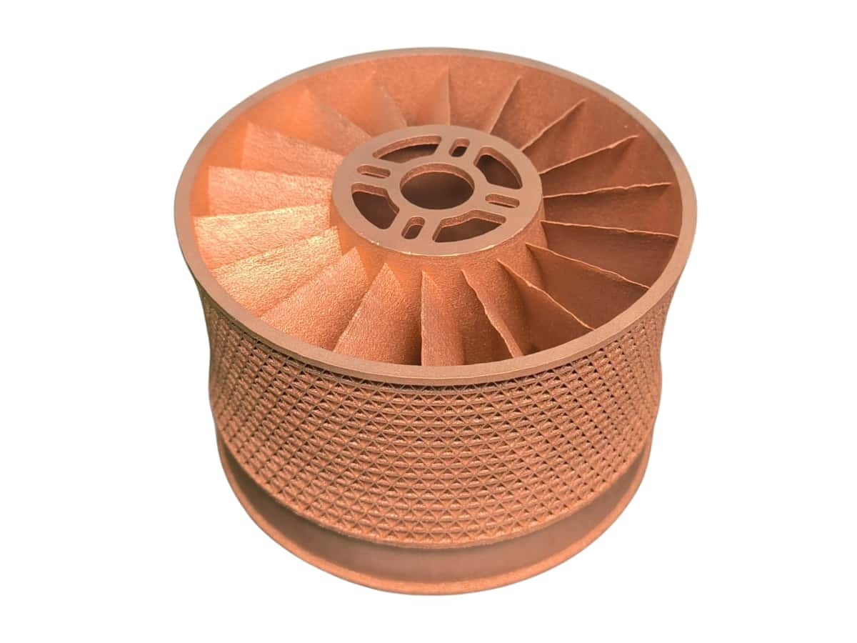
SLM Pure Copper

Back to Materials

SLM Pure Copper

Cu


3D printed copper leverages its superior thermal and electrical conductivity for demanding applications. Ideal for heat sinks, heat exchangers, and electrical components like inductors and bus bars, 3D printing enables complex designs and customization. Its high-temperature resistance also makes it suitable for aerospace applications. Explore the potential of this versatile material for optimized performance.


Min. Order Value $22

Est. Lead Time 7 days


Max Build Size

350 x 350 x 500 mm

Min Build Size

5 x 5 x 5 mm

Default Layer Height

0.05 mm

Optional Layer Heights

0.05 mm

Tolerance

卤0.2% (with a lower limit of 卤0.2 mm)

Heat Endurance

N/A


Smooth 鈽呪槄鈽

Detail 鈽呪槄鈽

Accuracy 鈽呪槄鈽

Rigidity 鈽呪槄鈽

Flexibility 鈽呪槄鈽

Available Colors

Bronze

Available Post Process

Polish

,

Sandblast

,

Electroplate

Gallery

Suitable For

Functional prototypes and end products,
Cases, holders, adapters,
Form and fit testing,
Functional prototyping and testing

Not Suitable For

Large models,
Cavities within design (unless making use of escape holes)

Additional Info

3D printed copper is opening up some exciting possibilities due to copper’s excellent thermal and electrical conductivity. Here are some of the key use cases:

1. Heat Management:

  • Heat sinks: Copper’s high thermal conductivity makes it perfect for heat sinks with complex geometries that maximize heat dissipation. This is crucial for electronics, especially in high-power devices.
  • Heat exchangers: 3D printing allows for the creation of intricate internal channels within heat exchangers, leading to more efficient heat transfer. This is valuable in aerospace, chemical processing, and other industries.
  • Cooling channels: Integrating cooling channels directly into tools or molds can improve the cooling process and extend their lifespan.

2. Electrical Components:

  • Induction coils: Copper’s conductivity is essential for induction coils used in various applications, from heating to welding. 3D printing allows for customized coil designs with optimized performance.
  • Bus bars: These thick conductors distribute power in electrical systems. 3D printing enables the creation of complex bus bar geometries for improved efficiency and space utilization.
  • Connectors and contacts: Copper’s conductivity makes it ideal for electrical connectors and contacts, and 3D printing allows for customized designs for specific applications.
  • Antennas: 3D printing can create complex antenna shapes for optimized signal transmission in various applications, including wireless communication and aerospace.

3. Aerospace and Rocketry:

  • Rocket engine components: Copper’s high-temperature resistance and thermal conductivity make it suitable for certain rocket engine parts, such as combustion chambers and nozzles.
  • Propulsion systems: 3D printed copper components can be used in advanced propulsion systems for satellites and spacecraft.

4. Medical Devices:

Customized prosthetics and orthotics: 3D printing allows for the creation of personalized medical devices with complex geometries and improved fit.
Surgical tools: Copper’s antimicrobial properties can be beneficial in surgical tools, and 3D printing allows for the creation of specialized instruments.

5. Other Applications:

  • Jewelry and decorative items: 3D printing allows for the creation of intricate copper designs for aesthetic purposes.
  • Molds and tooling: Copper’s thermal conductivity can be advantageous in molds and tooling for various manufacturing processes.
Min Supported Wall Thickness
A supported wall is one connected to other walls on two or more sides.
0.8 mm
Min Unsupported Wall Thickness
An unsupported wall is one connected to other walls on less than two sides.
1 mm
Min Supported Wires
A wire is a feature whose length is greater than five times its width. A supported wire is connected to walls on both sides.
0.8 mm
Min Unsupported Wires
A wire is a feature whose length is greater than five times its width. An unsupported wire is connected to walls on less than two sides.
1 mm
Min Hole Diameter
The accuracy of a hole not only depends on the diameter of the hole, but also on the thickness of the wall through which the hole is printed. The thicker the wall section, the less accurate the hole becomes. Through holes must also allow for line-of-sight clearance to ensure all material is cleared during post-processing.
1 mm
Min Embossed Detail
A detail is a feature whose length is less than twice its width.
The minimum detail is determined by the printer’s resolution.When detail dimensions are below the minimum, the printer may not be able to accurately replicate them. Details that are too small can also be smoothed over in the polishing process.
To ensure details come out clearly, make them larger than the indicated minimum. We may refrain from printing products with details smaller than the minimum, since the final product will not be true to your design. If your product has details smaller than the minimum, try making them larger, removing them, or considering a material with finer detail.
0.1 mm
Min Engraved Detail
A detail is a feature whose length is less than twice its width. Engraved or debossed details go into a surface.
0.5 mm
Min Clearance
Clearance is the space between any two parts, walls or wires.
To ensure a successful product, make the clearance between parts, walls, and wires greater than the indicated minimum. If your clearance is too small, try making the gap bigger, or consider fusing the parts or features if their independence is unnecessary. You can also try a material with a smaller minimum clearance.
0.6 mm
Min Escape Holes
Escape holes allow unbuilt material inside hollow products to be removed.
Normally you don’t need to consider this, our technician will add escape holes before printing.
When products contain hollow cavities, they are often filled with powder/liquid even after they are removed from the build tray. If escape holes are not large enough, or the geometry of the product makes it difficult to shake or blast the powder out, we cannot successfully clean it.
8 mm
Interlocking/moving or enclosed parts?
Sometimes the interlocking/moving parts can’t be printed, since the supports inside the cross section can’t be removed.
Require Support Material?
Because each layer needs to build off the last, for some material, angles of more than 45 degrees generally require supports to be printed along with the design. Supports are not inherently detrimental for your design, but they do add complexity to the printing process and lead to less smooth finish on overhanging parts.
Yes

Feature

Watertight

Foodsafe

Glueable

Recycleable

Biocompatible

Biodegradable

Flame Retardant

Conductive

Untested
Untested

3D Printer

Customized LCD Printer

Material Spec Sheet

SLM Pure Copper is 3D printed using SLM/DMLS (Selective Laser Melting) technology.

Selective Laser Melting Process

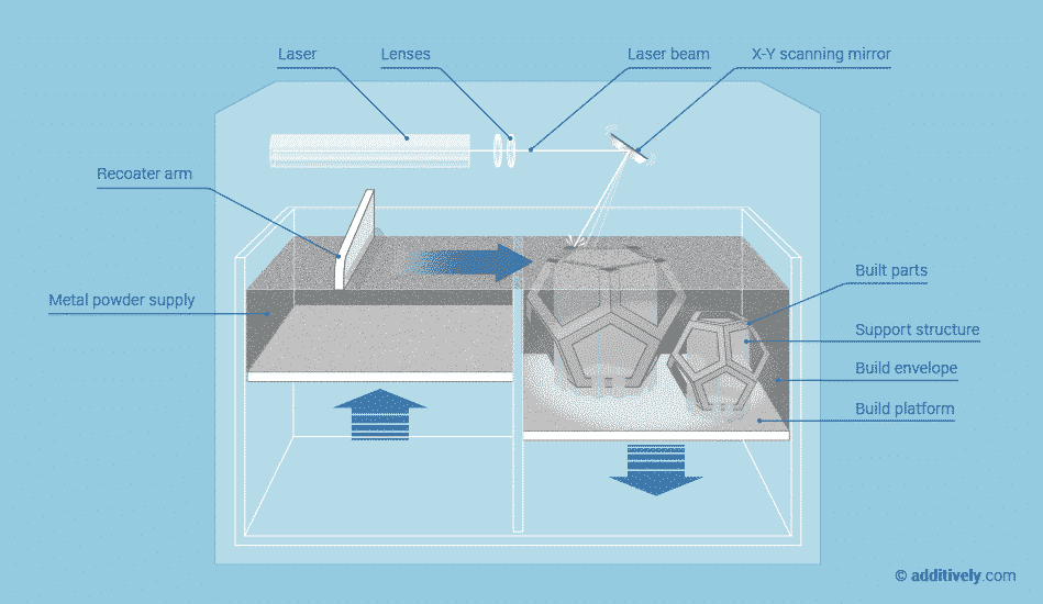
Selective Laser Melting creates objects from thin layers of powdered material by selectively melting it using a high power laser. The process takes place in a low oxygen environment in order to reduce thermal stresses and to prevent warping.

Industrial metals are best used for high-tech, low-volume use cases from prototyping to creating end-use parts. Metal 3D prints are comparable to traditionally manufactured parts in terms of chemical composition, mechanical properties (static and fatigue) as well as microstructure.

Once the printing is done, the extra powder that was not bound, and is not part of your design, is removed. Your part is now solid metal, and after the flutes are manually removed, it is tumbled and polished to produce a smooth finish.

How is SLM/DMLS 3D Printing Working?


銆2025-05-01銆

[Important Notice] Check our Labor Day holiday schedule (May.1-5) and US tariff policy explanation!

馃憠More detail
6% OFF for Insta3DP - Automatic 3D printing quotation! Coupon Code: insta3dpbeta2