MJF Nylon PA 11

Back to Materials

MJF Nylon PA11

HP 3D High Reusability PA11


This thermoplastic delivers optimal mechanical properties, ideal for strong, ductile, functional parts. It also has excellent chemical resistance and enhanced elongation-at-break. Ideal for impact resistance and ductility for prostheses, insoles, sports goods, snap fits, living hinges, and more.


Min. Order Value $44

Est. Lead Time 15 days


Max Build Size

380 x 284 x 380 mm

Min Build Size

5 x 5 x 5 mm

Default Layer Height

0.08 mm

Optional Layer Heights

0.08 mm

Tolerance

卤0.2% (with a lower limit of 卤0.2 mm)

Heat Endurance

Up to 110 鈩


Smooth 鈽呪槄鈽呪槄

Detail 鈽呪槄鈽呪槄

Accuracy 鈽呪槄鈽呪槄

Rigidity 鈽呪槄鈽

Flexibility 鈽呪槄鈽呪槄鈽

Available Colors

Grey

Available Post Process

Paint

Gallery

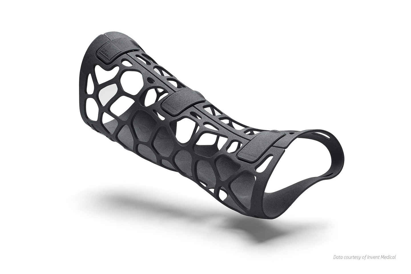
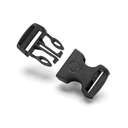
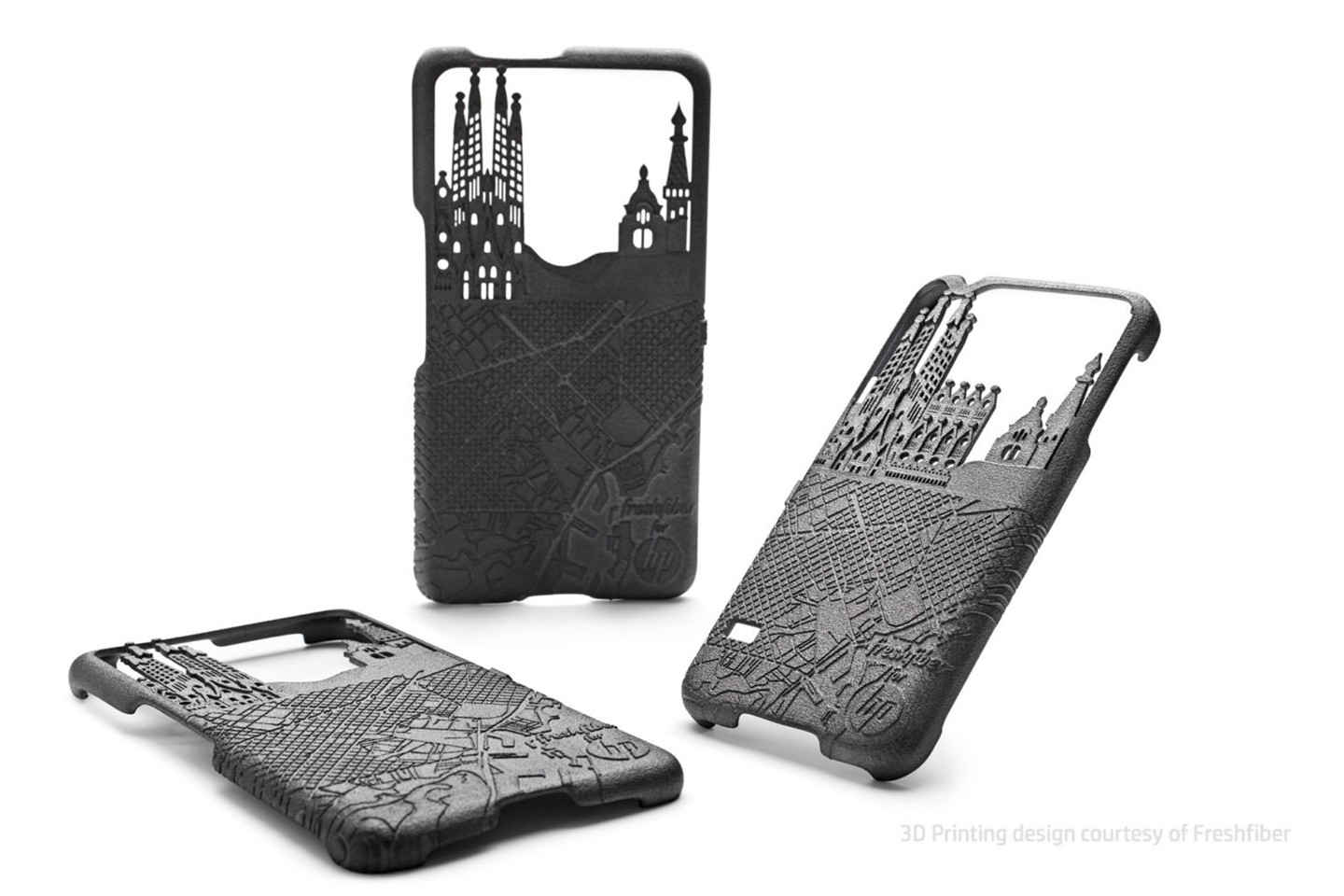
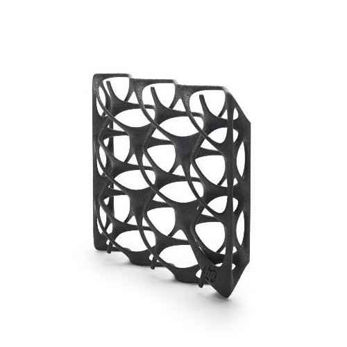
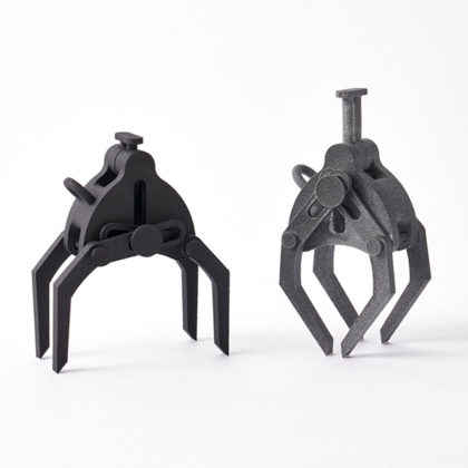
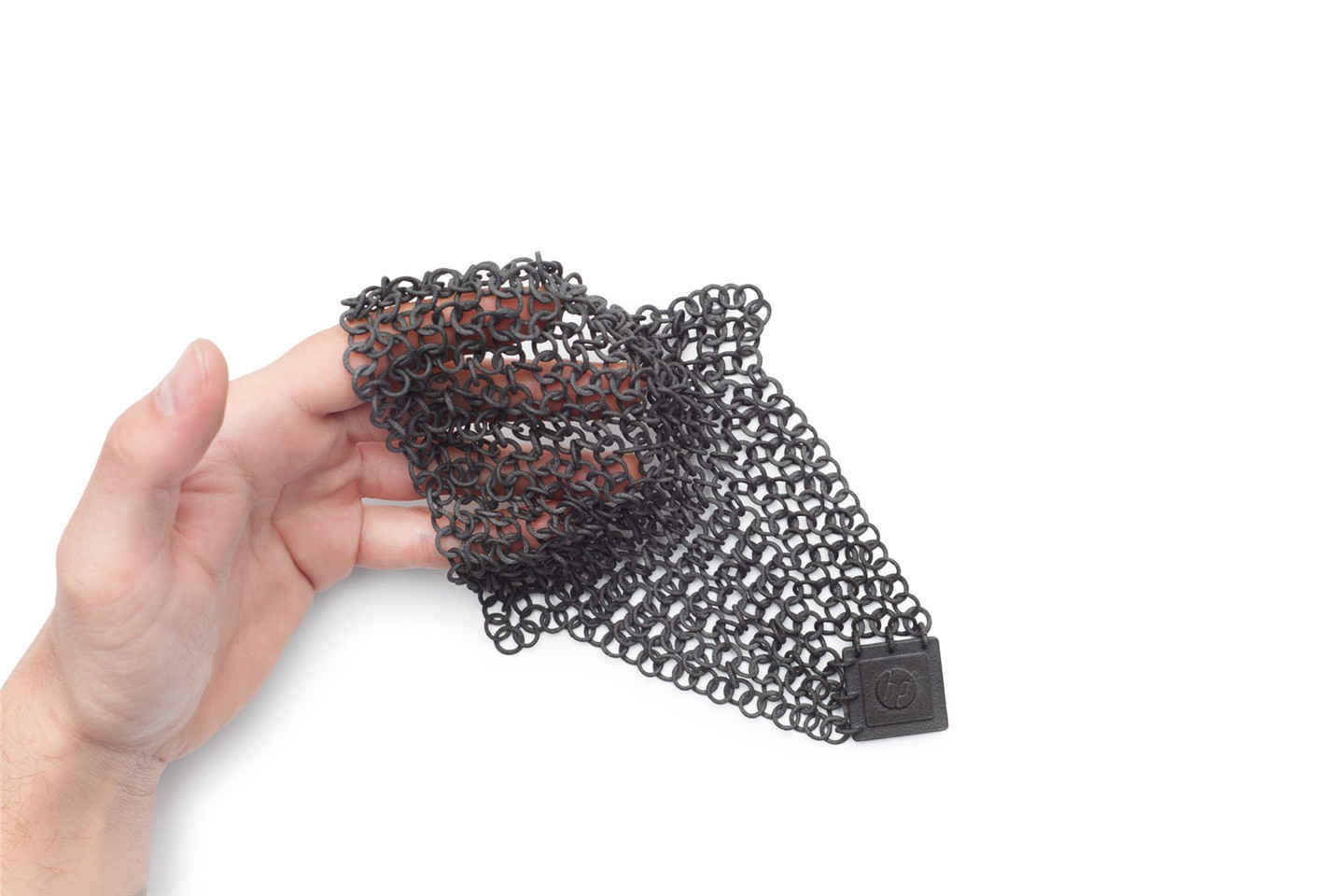
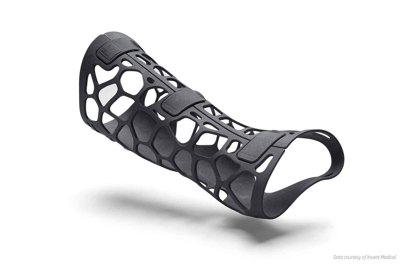
Suitable For

Functional prototypes and end products,
Complex designs with intricate details,
Moving and assembled parts,
Cases, holders, adapters,
Sales, marketing and exhibition models,
Form and fit testing,
Functional prototyping and testing

Not Suitable For

Cavities within design (unless making use of escape holes)

Additional Info

Produce strong, ductile, functional parts

鈥 Thermoplastic material delivering optimal mechanical properties.

鈥 Renewable raw material from vegetable castor oil (reduced environmental impact)

鈥 Provides excellent chemical resistance4 and enhanced elongation-at-break

鈥 Impact resistance and ductility for prostheses, insoles, sports goods, snap fits, living hinges, and more.

Min Supported Wall Thickness
A supported wall is one connected to other walls on two or more sides.
0.8 mm
Min Unsupported Wall Thickness
An unsupported wall is one connected to other walls on less than two sides.
1 mm
Min Supported Wires
A wire is a feature whose length is greater than five times its width. A supported wire is connected to walls on both sides.
0.8 mm
Min Unsupported Wires
A wire is a feature whose length is greater than five times its width. An unsupported wire is connected to walls on less than two sides.
1 mm
Min Hole Diameter
The accuracy of a hole not only depends on the diameter of the hole, but also on the thickness of the wall through which the hole is printed. The thicker the wall section, the less accurate the hole becomes. Through holes must also allow for line-of-sight clearance to ensure all material is cleared during post-processing.
1 mm
Min Embossed Detail
A detail is a feature whose length is less than twice its width.
The minimum detail is determined by the printer’s resolution.When detail dimensions are below the minimum, the printer may not be able to accurately replicate them. Details that are too small can also be smoothed over in the polishing process.
To ensure details come out clearly, make them larger than the indicated minimum. We may refrain from printing products with details smaller than the minimum, since the final product will not be true to your design. If your product has details smaller than the minimum, try making them larger, removing them, or considering a material with finer detail.
0.4 mm
Min Engraved Detail
A detail is a feature whose length is less than twice its width. Engraved or debossed details go into a surface.
0.4 mm
Min Clearance
Clearance is the space between any two parts, walls or wires.
To ensure a successful product, make the clearance between parts, walls, and wires greater than the indicated minimum. If your clearance is too small, try making the gap bigger, or consider fusing the parts or features if their independence is unnecessary. You can also try a material with a smaller minimum clearance.
0.5 mm
Min Escape Holes
Escape holes allow unbuilt material inside hollow products to be removed.
Normally you don’t need to consider this, our technician will add escape holes before printing.
When products contain hollow cavities, they are often filled with powder/liquid even after they are removed from the build tray. If escape holes are not large enough, or the geometry of the product makes it difficult to shake or blast the powder out, we cannot successfully clean it.
8 mm
Interlocking/moving or enclosed parts?
Sometimes the interlocking/moving parts can’t be printed, since the supports inside the cross section can’t be removed.
Require Support Material?
Because each layer needs to build off the last, for some material, angles of more than 45 degrees generally require supports to be printed along with the design. Supports are not inherently detrimental for your design, but they do add complexity to the printing process and lead to less smooth finish on overhanging parts.
No

Feature

Watertight

Foodsafe

Glueable

Recycleable

Biocompatible

Biodegradable

Flame Retardant

Conductive

Untested
Untested

Material Spec Sheet

MJF Nylon PA11 is 3D printed using MJF (Multi Jet Fusion) technology.

Multi Jet Fusion Process

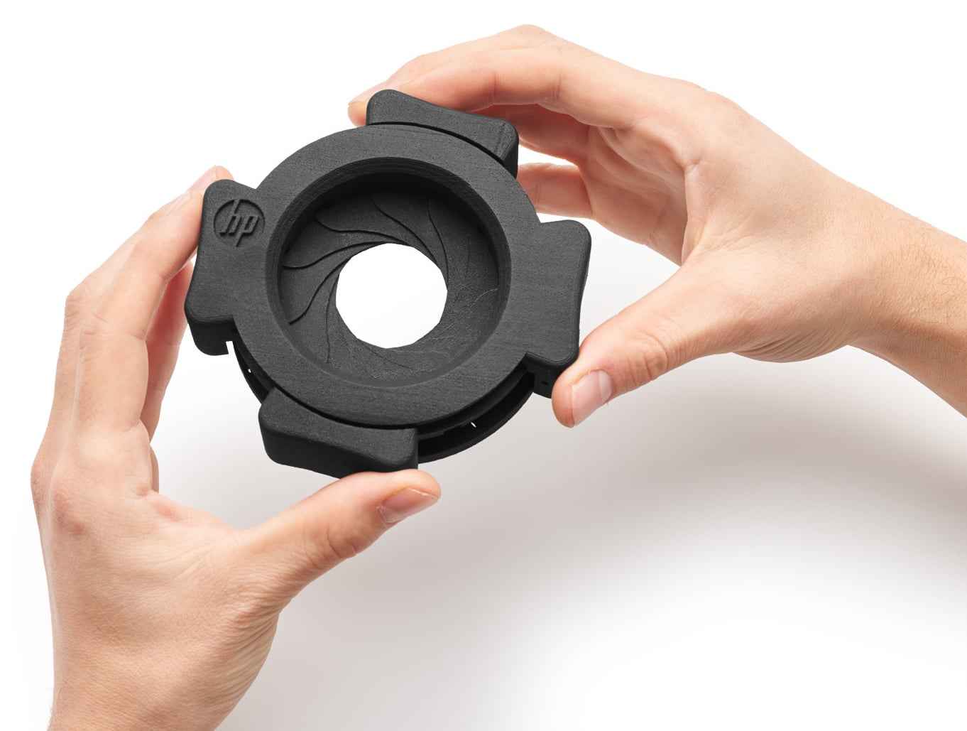
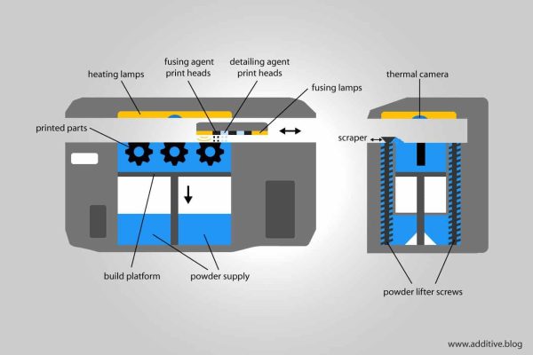
In this process a fusing agent is applied on a material layer where the particles are destined to fuse together. Then a detailing agent is applied to modify fusing and create fine detail and smooth surfaces. To finish, the area is exposed to energy that will lead reactions between the agents and the material to create the part.

When the printing process is complete, the build box is removed from the printer. An operator carefully extracts the parts from the build box and removes the remaining powder thanks to brushes and air blowers.

How is MJF 3D Printing Working?