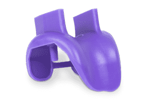
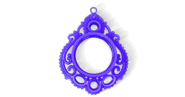
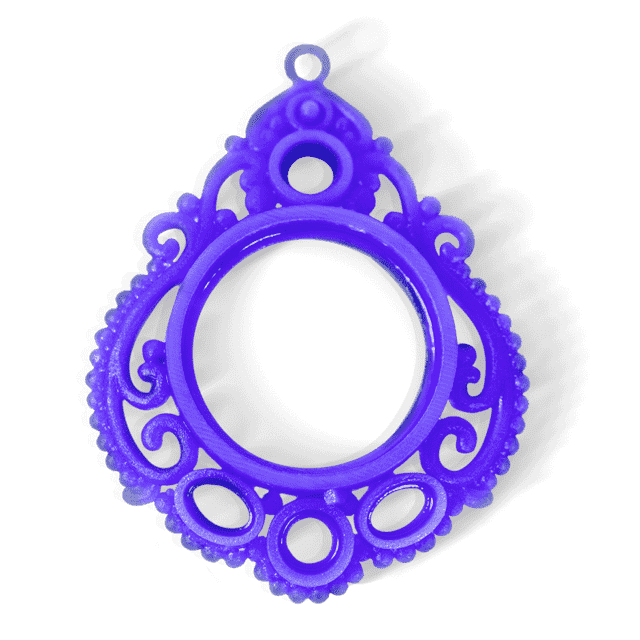
 3D Systems Castable Wax3D Systems Visijet M2 CAST Castable Wax has a rich blue color, and a weight and surface feel similar to traditional candle wax. Wax products sometimes have white patches caused by slight remnants of the support material, but these should not affect the wax’ castability or the final cast product. Max Build Size Min Build Size 2 x 2 x 2 mm Default Layer Height 0.016 mm Optional Layer Heights 0.016, 0.032 mm Tolerance Âḟ0.1 mm Up to 40 â Smooth â â â â â Detail â â â â â Accuracy â â â â Rigidity â Flexibility â Available ColorsPurple
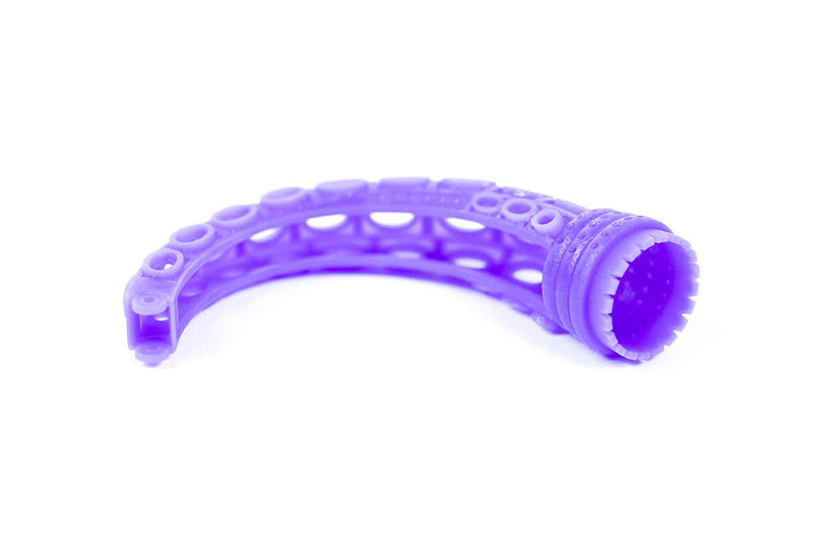
Available Post ProcessSuitable For Complex designs with intricate details, Not Suitable For Functional prototypes and end products, Additional InfoRules and Recommendations Because Wax products are intended for casting, we have included two values for each design guideline: a rule and a recommendation. The rules are based on what think we can successfully produce in Wax, and we will try to create all products that meet them. The recommendations are based on what we have seen that can be successfully cast into metal. If you do not have extensive casting experience, we strongly suggest that you design based on the recommendations. Design for Shippability Wax is incredibly fragile, and can break during shipping despite our best packaging efforts. Keep this in mind when designing your Wax product. Large models with thin wires are particularly susceptible to breakage in shipping.
Feature
3D PrinterMaterial Spec Sheet
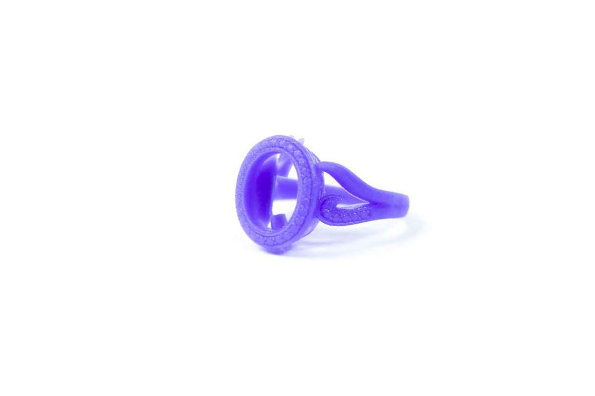
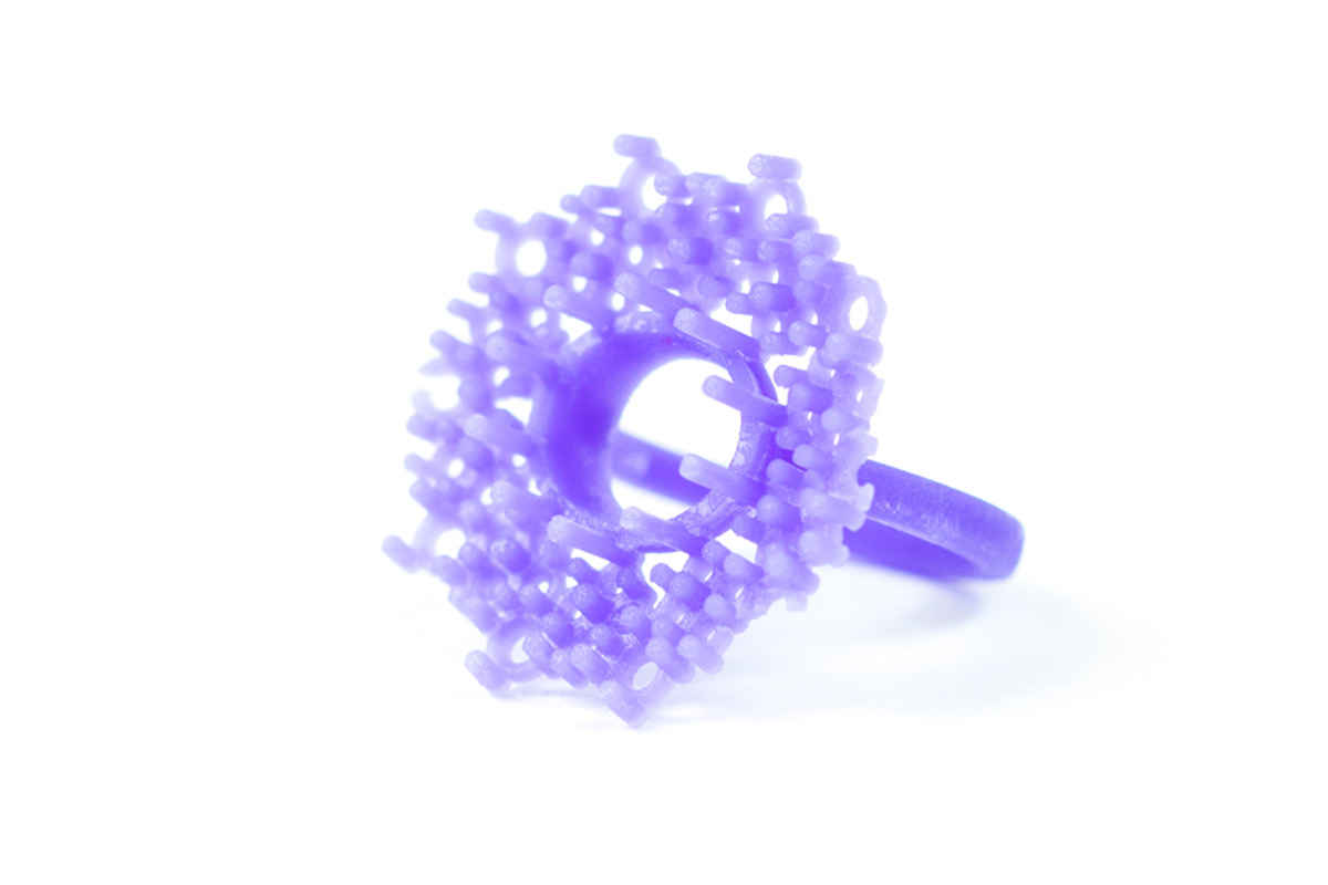
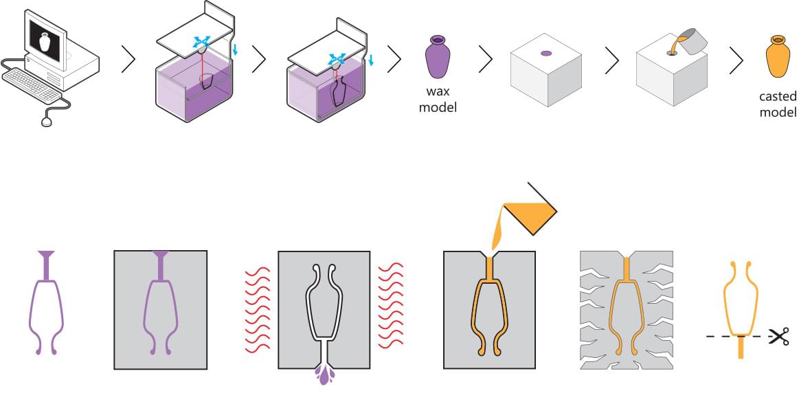
Wax 3D printing and lost-wax casting are used to build your design when using this material. The wax printing process is a type of Stereolithography/Multi material jetting that uses a wax-like resin. Support structures are printed along with the model to make sure your model doesnât fall apart. These support structures are automatically generated and manually removed after the printing process. After support structures are removed and your model is cleaned, the model can be prepared for casting. First, one or more wax sprues will be attached to your model. Next, the sprue and model will be attached to a wax âtreeâ, together with a bunch of other models. The tree is then placed in a flask and covered in fine plaster. When the plaster solidifies, it forms a mold for copper casting. The plaster mold is then put in an oven and heated for several hours to a point where the wax is completely burned out. Then, molten copper is poured in to fill the cavities left by the wax. Once the copper has cooled and solidified, the plaster mold is broken and the copper models are removed by hand. Then, your model is filed and sanded to get rid of the sprues, and finally polished.
|