Gallery
About Project
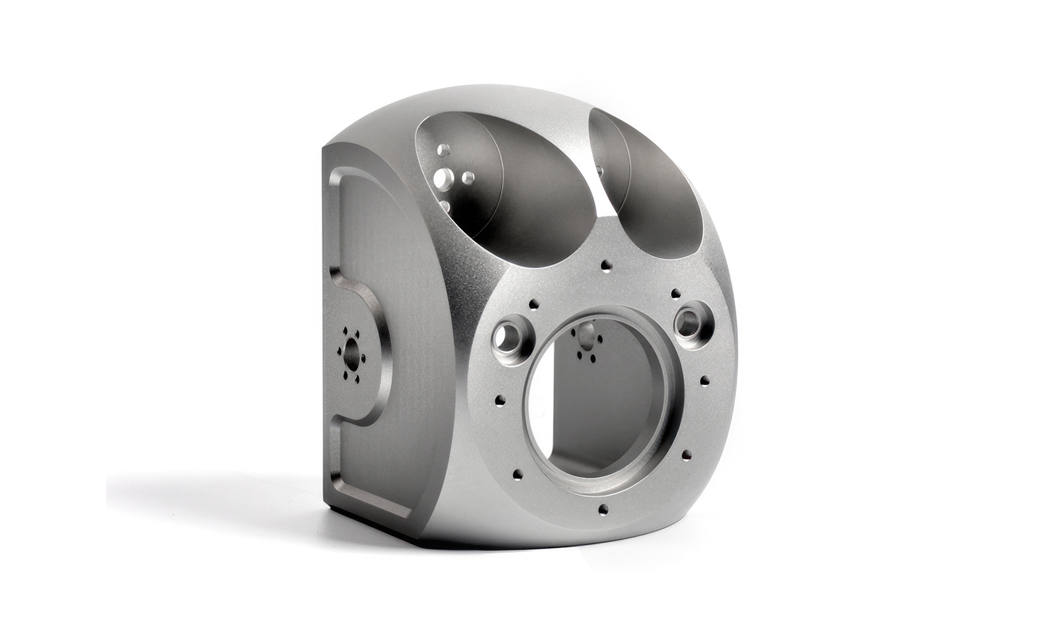
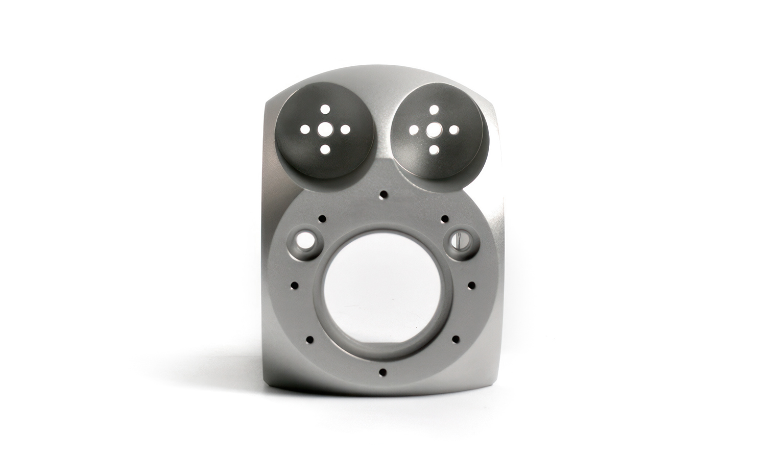
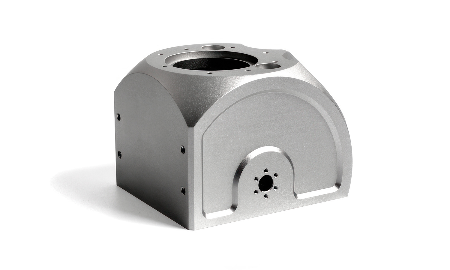
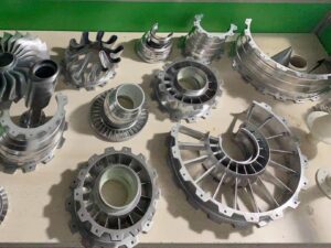
This part looks like a precision aluminum housing for a compact gearbox or actuator assembly. The design is a good example of how modern mechanical products balance stiffness, weight, and manufacturability in one structural component.
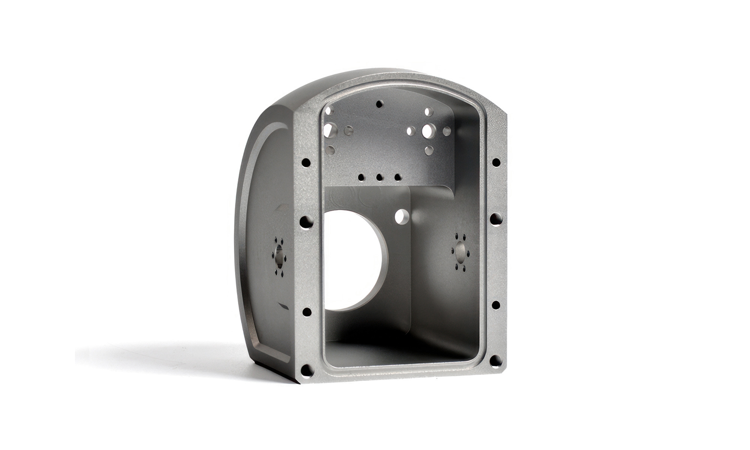
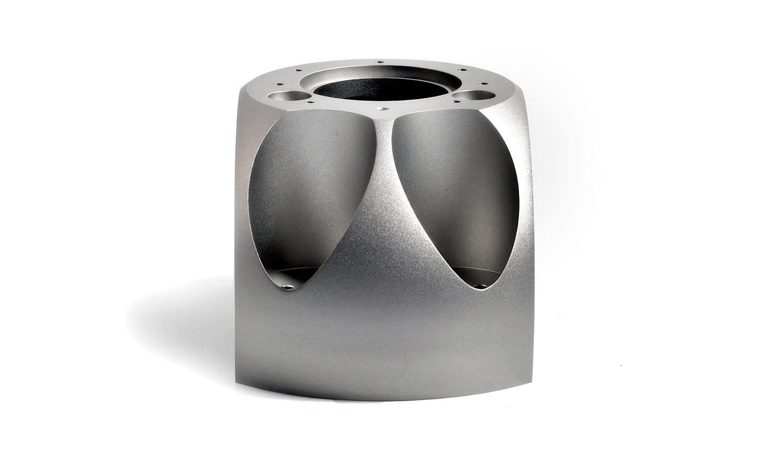
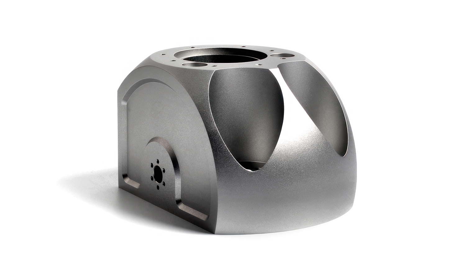
At the front, a large central bore is surrounded by a bolt circle, suggesting an interface for a bearing seat, a shaft pass-through, or a mating flange to another module. Around it, you can see carefully placed drilled and counterbored holes for fasteners, alignment features, and possibly sensor or port mounting. On the top, the two deep pockets support weight reduction while preserving rigidity, and they also create clearance for internal rotating components or cable routing. The large side windows and internal cavities serve a similar purpose, trimming mass and improving access while keeping the outside geometry clean and robust.
From a manufacturing standpoint, this is a classic 5-axis CNC job: roughing to remove bulk material, semi-finishing to stabilize the part, and finishing passes to achieve tight tolerances on critical bores and mounting faces. Details like consistent fillets, smooth pocket transitions, and well planned hole patterns hint that this component was designed with both performance and machining efficiency in mind.
If you are building similar precision housings and need reliable CNC machining from prototype to production, FacFox can help. FacFoxŌĆÖs CNC services support complex 5-axis parts with tight tolerance control, consistent surface finishes, and a wide selection of metals including aluminum alloys. Upload your CAD, get fast quotes, and work with experienced partners who understand critical features like bearing bores, mating faces, and hole positional accuracy.
Solution
- Step 1: The aluminum alloy billet was cut to size and the blank was labeled for traceability.
- Step 2: The blank was fixtured on a CNC machining center, and datums were established by facing the first reference surface.
- Step 3: The overall outer profile was roughed and then semi finished, and the part was flipped to face the opposite side to final thickness.
- Step 4: Major pockets and weight reduction cavities were roughed with high material removal toolpaths, leaving stock for finishing.
- Step 5: Internal windows and side cutouts were milled, and corner radii were formed with appropriate end mills to match design fillets.
- Step 6: Critical circular features were machined, and the central bore was interpolated and finished to the required diameter and roundness.
- Step 7: Bolt circles and mounting holes were drilled, counterbored, and tapped as specified, and hole patterns were completed from the established datums.
- Step 8: Precision faces and sealing or mating surfaces were finish milled, and chamfers were added to protect edges and improve assembly.
- Step 9: All burrs were removed, and the part was cleaned to eliminate chips and coolant residues from internal cavities.
- Step 10: Dimensional inspection was performed, and critical features such as the bore size, hole positions, and flatness were verified with CMM or gauges.
- Step 11: A surface finish treatment was applied if required, such as bead blasting or anodizing, and the part was final cleaned and packed.

