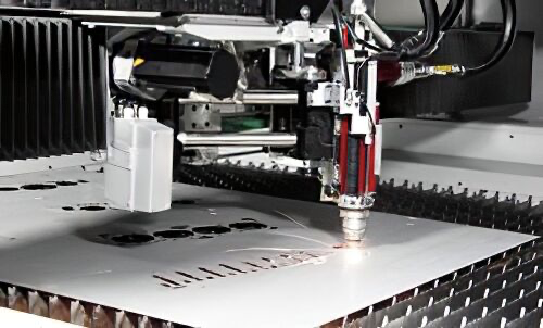
When CO2 laser cutting machines made their debut on the metal fabricating scene in a big way in the 1980s, people wondered about the future of the punch press. How could traditional punching technology compete with a machine tool that required no tooling to create holes and shapes?

Well, history has shown that CO2 laser cutting wasn’t the end of punching. In fact, precision punch presses still remain the technology of choice for those fabricators that produce a high volume of blanks with consistently sized punchouts. Laser cutting machines have emerged, on the other hand, as more flexible fabricating tools. Each contributes in a unique way to the success of a job shop.
But as more metal fabricators look to eliminate material handling of parts during production, they are seeking to accomplish more tasks while the blank sits in the bed of the machine tool. It’s one of the reasons fabricators are pushing their laser cutting machines to provide that most basic of fabricating activities: hole cutting.
A metal fabricator may need to create some perforated sheet, but doesn’t have the volume necessary to use a punch press; in this case, the laser can quickly knock out the holes and complete the job. Or perhaps the shop wants precisely cut holes to accommodate tapping or create a through-hole for some sort of support piece for the final assembly; in this case, the laser cutting machine’s ability to deliver a high-tolerance hole eliminates secondary drilling activities down the line.
These modern fabricating machines can accomplish such tasks thanks to advances in drive technology, piercing capabilities, and control software. These aren’t the machines from 20 years ago, which might have struggled with inconsistent beam delivery and with the effects of ambient heat on consistency. Today’s machines are up for the whole task of hole cutting in thin materials.
Drive to Cut Better
If a laser cutting machine is to deliver a high-tolerance hole, the cutting head needs to be in the correct position. “The more precise you can position your laser beam, the more precise is your hole,” said Stefan Fickenscher, TRUMPF’s product manager, 2-D laser cutting.

The same principle applies to punch presses.
“Realistically, it would be the same thing with a punching machine—how accurately you would position the sheet in turn relates to how accurately the hole would be positioned in the part. It’s a matter of moving the cutting head,” said Brian Welz, TRUMPF’s applications manager.
For many years ball screw-driven technology powered the cutting head over the laser cutting machine bed. The technology proved very effective in precisely positioning the cutting head where it needed to be. Keith Leuthold, director of inside sales, Mazak Optonics, put the positioning accuracy of a ball screw-driven system at approximately ±0.0004 inch.
“But it can’t rapid-traverse very quickly, meaning not so much in cutting, but actually bouncing from one feature of a part to another,” Leuthold said.
That led to the adoption of rack-and-pinion drive systems, which bumped up the traverse speeds, but couldn’t offer as much precision as the ball screw technology, according to Leuthold.
Over the past 10 years, however, the industry has introduced to a new drive technology option—linear drives. This was a major move away from the use of rotary motion toward linear motion.
Unlike a rotary motor, in which magnets interact with coils to turn the shaft repeatedly, a linear-drive motor has magnets lined up side-by-side along a fixed track, which interact with the electrical windings in the moving component. When the current flows through the windings, the component moves along the track. The moving component moves the load, in this case the cutting head, to the desired location. An encoder ensures the precise location of the cutting head.
“What linear drives have allowed us and others to do is to enjoy the best of both worlds. They are extremely precise and extremely quick. The response time is now measured in G-forces. Some machines are up to 3G or 4G in acceleration and deceleration,” Leuthold said.
Linear-drive systems aren’t the only choice for metal fabricators, however. Rack-and-pinion systems still are used widely because of their reliability and affordability. In fact, the technology continues to improve to keep up with the speed of solid-state lasers that increasingly are finding a home in metal fabricating shops.
Salvagnini introduced a patented drive system in North America in 2011 that was specifically designed for fiber laser cutting (see Figure 1). (In fiber laser cutting, a solid-state laser beam is produced when diode lasers emit specific electromagnetic wavelengths into optical fibers, similar to the ones used in the communications industry. The laser energy that is created in those optical fibers is then fed through a transport optical fiber to the cutting head.) The focusing head positioner is driven by a pair of rotary motors, allowing the cutting head to move over a distance of 6.7 in. This X-Y subaxes approach is not new to laser cutting, but it is different in the sense that the cutting head is not burdened with the added weight of a dedicated cooling system or optical scales.
“We actually don’t change anything on the major X and Y axes. The positioning head, because of its light weight, can be accelerated very quickly,” said Salvagnini America President Bill Bossard. “It actually eliminates the need for linear drives to gain high performance when cutting those laser nests that have a lot of attributes very close together. It is quickly moving by itself without even moving the major axes very much.”
Bossard said the cutting head can reach an acceleration of up to 5G, which helps to knock out more parts per hour—even if those parts have a lot of holes. (For more on the hole-cutting prowess of fiber lasers, see Fiber Finds Its Way sidebar.)
So today’s modern laser cutting machines have drive systems that can get the cutting head in precise position in the blink of an eye, but what happens as the laser is about to make that initial cut?
Piercing Insight
Before it can make a hole, the laser first needs to pierce the metal. That step sets the stage for the rest of the cut.
For many years metal fabricators had to rely on step, or peck, piercing to produce precise holes. The cutting head lingered over a spot until the laser cut through the material. Unfortunately, it took several seconds; for thick materials, it could take as long as 25 seconds. Additionally, the prolonged cutting process exposed the metal to plenty of heat, which increased the risk of metallurgical changes.
Later, machine tool builders introduced the concept of blast piercing. The resonator was turned up for maximum power, and the shutter was opened to release a powerful burst of energy.
“It blows right through it,” Leuthold said.
Unfortunately, this blasting created a volcanic effect, where molten metal blew up and left splatter all over the sheet metal. The large release of laser power also produced craters, which did little to improve the technology’s ability to make small, precise holes.
Advanced control technology helped to refine the piercing power of modern laser cutting machines. Now sensors are used to detect when an increase or a decrease in laser power might be needed to deliver a clean, quick pierce (see Figure 2).
“What the sensors are doing now is they are really monitoring the beam deflection,” Fickenscher said. “When the beam deflection is getting higher, we are going down with the laser power. And if there is a little bit of beam deflection, then we are going up.”
“This gives us the opportunity to make smaller holes even in thicker materials,” Welz added. “Not only to make it, but to do it consistently and in a repeatable way, which is a key to production.”
Leuthold added that this approach has helped to limit that amount of material deformation that might take place in the sheet metal blank, because the material is no longer exposed to heat for a long period of time.
“In fact, we are getting holes just as precise or better than we did with step piercing, but at the speeds of blast piercing,” he said.
Another recent development has been the introduction of on-the-fly piercing. Instead of the cutting head piercing the material in the middle of the intended hole, the pierce is actually made directly on the contour of the hole with the cutting head at full speed.
Fickenscher said this approach is suitable when a metal fabricator wants to make the maximum number of holes in a minimum amount of time. The on-the-fly pierce does diminish the quality of the hole somewhat because the pierce takes place on the edge of the hole, but the metal fabricator that favors this type of a pierce is more likely interested in speed than hole quality.
The Balance Between Speed and Quality
In a way, the same conundrum that existed more than 25 years ago exists today. The advances in drive system, piercing, and even control technology allow laser cutting machines to deliver good hole-cutting performance, but if the metal fabricating shop pushes the limits of the machine, overall quality may suffer.
“There is an understanding that there is a give and take in a manufacturing process,” Welz said. “In order to achieve consistency, other things need to be given back. On the other hand, when you give up that consistency, you get the other ones back—speed and processing. You need to weigh one against the other.”
Laser cutting machines can do remarkable things, especially compared to technology that is 10 years or older, but they aren’t designed to surpass the laser cutting machine manufacturer’s specifications for extended periods of time. So if a blue arc is present during hole cutting with nitrogen or excessive sparking occurs during cutting, the operator might just want to slow down.
Fiber Finds Its Way
The generally accepted rule in hole cutting is that the minimum hole size should be no less than the material thickness.
Fiber laser cutting challenges that guideline, according to Steve Aleshin, a Salvagnini applications manager.
“What we have found with the fiber laser is that we can get down to a quarter of material thickness,” he said. “It’s difficult, for example in 0.5-in. material, to measure the quality of the hole when you get that small—to see inside of there without cutting things up. And certainly the customer will have to make the decision if that is a good enough hole.
“But we are making pretty decent holes, down to 3 mm in 12-mm material. It is a straight hole.”
Aleshin added that fiber laser cutting seems to avoid the hassles of producing plasma during cutting with nitrogen because of its wavelength. A fiber-generated laser beam has a wavelength of 1.064 microns; a CO2 resonator-generated laser beam has a wavelength of 10.6 microns.
“This is probably more with thinner materials—say 11 gauge or below,” Aleshin said. “You get the plasma [with CO2 laser cutting], so many times that you have to reduce your gas flow to help to reduce that plasma size. Then when you start to cut you have to increase your gas flow. Of course, all of this takes time.
“With the fiber laser, the plasma doesn’t affect the laser because of the wavelength. The full energy of the fiber laser still passes through the plasma, so it really doesn’t affect your cutting parameters,” he added. “So you save time because you keep the gas pressure consistent.”


Leave A Comment