Anisoprint is a company operating at the forefront of composite materials and additive manufacturing. Founded in 2015, the company has brought to market a series of turnkey solutions for continuous fiber 3D printing for the production of industrial end-use parts. These solutions, along with Anisoprint’s in-depth material and engineering expertise, are unlocking new opportunities for higher performing and more efficient parts with anisotropic properties.
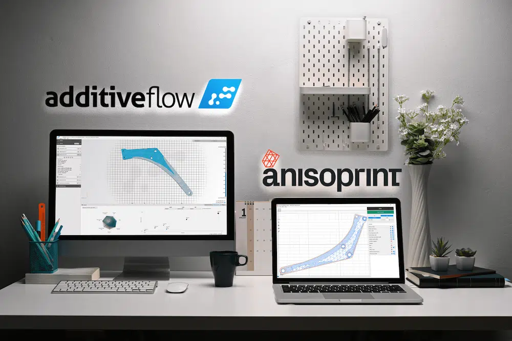
But the hardware is only part of the equation. Like any additive manufacturing technology, Anisoprint’s composite 3D printing solutions consist of many products, like materials and, crucially, software. From part design, optimization and simulation to slicing and printing, software unveils the potential of continuous fiber 3D printing. In recognition of this, Anisoprint and UK-based simulation software company Additive Flow have come up with a solution that combines Formflow, Additive Flow’s integrated optimization tool with Anisoprint’s Aura slicer.
To better understand what benefits the combined software solution brings to users, we spoke to Anisoprint CEO Fedor Antonov and Additive Flow CEO Alexander Pluke. What follows is a highly insightful conversation that not only illustrates the complexity of modeling for advanced composite materials but also introduces a new framework for reliable and reasonable design for additive manufacturing (DfAM).
Building the foundation for composite DfAM
“20 years ago, 3D printing was mostly used for prototyping, so there was no demand or need for DfAM,” Antonov begins by explaining. “Now that 3D printing has evolved for the production of end-use parts, design is critical as the possibilities of AM are only revealed with the right design approach. And every technology requires a certain design approach.”

From another perspective, 3D printing and advanced CAD tools can be seen as having existed in parallel. (The former limited by its use as a prototyping technology and the latter held back by the difficulty of translating its complex designs to existing manufacturing methods.) Today, the two sides are coming together, with 3D printing positioned as the most viable way to produce complex, optimized geometries. “Now the machine and manufacturer and designers speak the same digital language,” Antonov adds.
With more traditional 3D printing materials, like polymers and metals, design for AM is complex but fairly straightforward since geometries are generated based on the materials’ isotropic properties. Composite anisotropic materials, however, bring with them greater complexity and greater optimization potential.
“When we talk about composites, we are talking about anisotropic materials,” Antonov continues. “This is another level of both complexity and freedom of design. Metals and polymers have just a few property values which describe their behavior; for anisotropic materials, there are many more parameters that describe the material’s behavior in all directions. In other words, when we do generative design for isotropic materials, we are only talking about geometry and shape optimization. With anisotropic materials, we are also talking about material directionality. That’s another optimization space that will allow for superior results compared to isotropic materials. This is the biggest benefit of composites.”
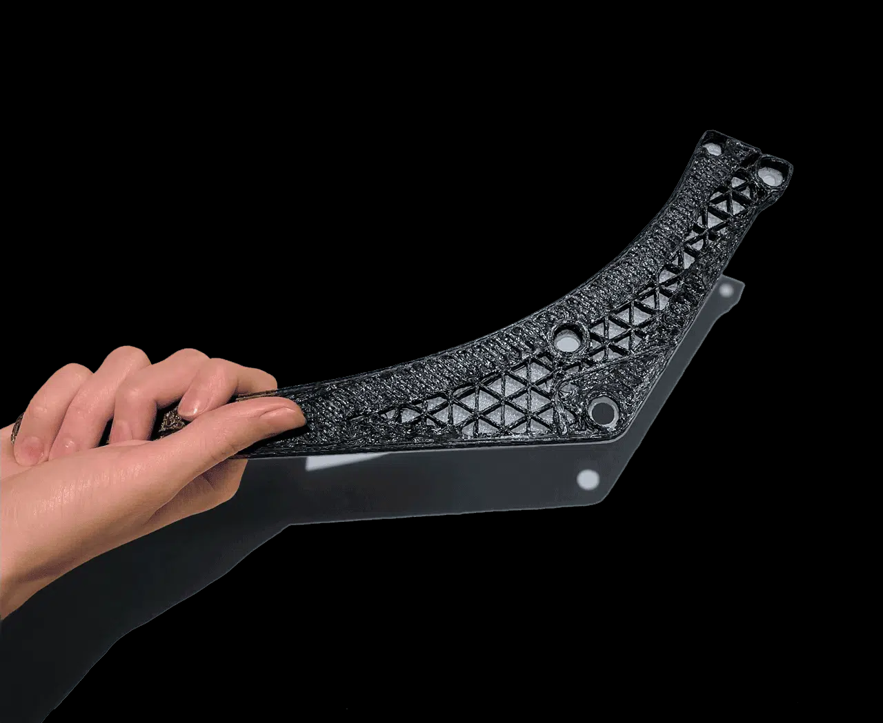
In practice, composite additive manufacturing relies on the ability to not only set part geometries and internal structures like lattices but also to control local fiber alignment within the part. This capability enables manufacturers to produce high-performance parts that are optimized for their specific loading conditions and stress fields.
Optimizing material properties efficiently
In order to achieve this level of control for composite 3D printed materials, however, we need the software tools to back it up. “We need an optimization tool that can create optimal structures with anisotropic composite materials by actually optimizing the geometry and the fiber direction at every point,” Antonov says. “It is possible, but nobody has ever done it to the full extent because not only is it difficult in terms of design but also extremely challenging in terms of translating the design to machine language.

“How do you go from a 3D model with all this directionality of materials to the actual tool path of the machine? This is a very complex problem which hasn’t been solved so far. But there is a very elegant solution that we’ve developed together with Additive Flow and which we are now implementing through the joint workflow of Formflow and Aura.”
Specifically, the two companies have overcome the complex problem of controlling the directionality of fibers at every point by simplifying the process. “Instead of optimizing material directionality at every point—what we call continuously—you can optimize materials discretely,” he says. “Not in every point, but in every domain or subdomain. So you have your design space where your 3D model sits and within this space you can have different domains with different material properties.”
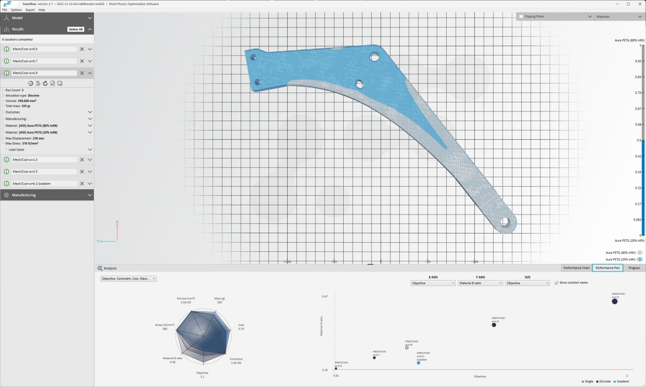
“For example, if you have a beam structure that will work in bending, the optimal design will have a sparse structure in the middle and two stiff parts on the top and bottom, like a sandwich. These will be the different domains with different material properties,” Antonov adds. Additive Flow’s Formflow software therefore enables the automated generation of anisotropic models, which can then be sliced in Aura and 3D printed using Anisoprint’s 3D printers. Aura, for its part, translates the variable directionality of the composite materials into a toolpath using its unique mask function.
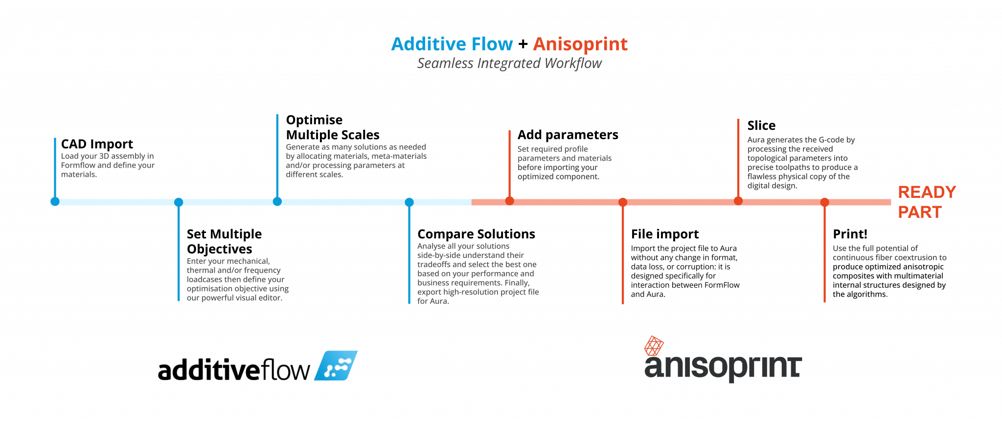
There are three overarching interactions between Formflow and Aura:
Manufacturing on Demand
- Full extent of the Composite Fiber Co-Extrusion (CFC) technology. The combination of Additive Flow’s optimization and the Aura slicer reveals the full potential in Anisoprint’s CFC technology. It enables Anisoprint’s Composer 3D printer to produce anisotropic components with highly complex multimaterial internal structures designed by algorithms.
- Seamless integration. Aura and Formflow share the file format and the slicer imports the model without any change in format, data loss or corruption. No time is wasted between exporting the model from the Formflow solution and slicing it by Aura.
- Masks in Aura allow the processing of different internal structures for the best material properties that meet specific local needs. Customizing internal structures, or dividing the space inside into a finite number of areas and setting parameters individually for each that best meet requirements, is the key to Anisoprinting models optimized by Formflow.
From design to decision-making
There is also another dimension to the Formflow optimization solution that Additive Flow CEO Alexander Pluke highlights. It is centered on the workflow of creating optimized parts and processes for 3D printing and streamlining the parameters users must input. To better understand the role Additive Flow’s software has, he proposes thinking not only about “design” but instead about “decision making”.
“I think when we focus just on the word design we can actually inhibit the development of AM because when people think design, they stop thinking about manufacturing,” he elaborates. “This kind of denigrates what is happening in the workflow, because we’re not just optimizing design, we’re making decisions across every matrix that can be changed and building relationships between decisions at every scale and the impact that decisions will make on your key objectives.”
The key objectives he references encompass many things, from engineering goals (including weight, mechanical and thermal requirements, among others), to cost goals and sustainability goals. “You have this constant battle in the head of a decision maker, because they have to understand the impact of every choice and decision they make,” he says. “‘What’s the shape? What’s the orientation of the fiber? What lattice structure am I going to use? If I use a lattice, what orientation is the whole lattice structure on?’ These are the decisions one has to make, all while balancing it against their key goals.”
And that’s only one aspect of the decisions that go into producing an optimized anisotropic component. You also have manufacturing decisions, including machine parameters, toolpaths, layer height, etc. As Pluke says, “You don’t just have different scales of decision, you also have different stages of decision. And one of the big frictions in this process is different software tools, different workflows, like CAD design, optimization tools, like topology optimization and generative design, and eventually the slicer software.”
In other words, what we traditionally call the “design” process in AM is far more complex because it encompasses so many different elements and each requires many decisions. What Formflow does is compress many of these decisions to streamline the design-to-production workflow.
Meeting multiple objectives in one workflow
“We’ve built three key features. First is the ability to have multi-objective optimization,” Pluke explains. “For example, you can input your engineering goals, as well as your target cost and target sustainability goals. The second feature is called volumetric optimization. This is where different regions of the design space are assigned different properties. And it’s not just one property, you have whether a lattice exists or not, how dense the lattice is, what is the orientation of the lattice, etc.”
With Anisoprint’s technology, even more properties come into play that aren’t relevant to other non-composite 3D printing technologies. The software accounts for things like fiber direction and the material chemistry. In the future, Pluke reveals the software could even have properties for things like solidification rate and the temperature used to melt the material, because they also have an impact on part outcomes and production speeds. “Our technology can look at all these scales simultaneously and then volumetrically allocate and tune these variables spatially based on the multi-objective function,” Pluke says.
“And the third key feature is the digital thread. This is where we not only look at one stage (ie. design, or manufacturing), but at how all the stages link up. In order to create these links, our software communicates and connects to the full workflow. For example, we integrate with Anisoprint’s Aura slicing technology. Ultimately, instead of making 1000 different decisions, you just have to make two: what are my goals and what freedom do I have?”
From there, users can scale easily to optimize many different 3D printed parts based on the same objectives. “Once you’ve set up the multi-objective function, you can repeat that function again and again in a geometry agnostic way. For example, if a client in the aerospace industry is optimizing an airplane bracket, they can take that same workflow and objective and apply it to a radio frequency component.” This saves engineers significant time and unlocks scalability for the whole process.
“The decision maker doesn’t need to get bogged down in the details,” Pluke continues. Instead, they just need to choose from a set of solutions that are evaluated based on their cost, sustainability and engineering goals. From there, the file can be seamlessly sent to Aura and 3D printed. With Anisoprint specifically, the complexity of the continuous fiber 3D printing process and the additional properties it introduces—like fiber direction—creates more room for optimization. “Additive Flow offers a seamless, straightforward way of harnessing that complexity,” he states.
“Continuous fiber 3D printing technology is actually one of the most demanding when it comes to making these decisions,” Antonov concludes. “It can perform very badly if you don’t know how to design for the technology. But if you do optimize parts properly, it has real benefits and outperforms almost any other materials. We need tools like Additive Flow’s software to achieve those optimal results.”
This article was originally published in 3dpbm’s Advanced Polymers AM Focus eBook 2022 in cooperation with Anisoprint.
* This article is reprinted from 3D Printing Media Network. If you are involved in infringement, please contact us to delete it.
Author: Tess Boissonneault


Leave A Comment