Whether you’re designing a lifesaving medical device or the next great garden hose bib, investing $50,000 or more—often much more—in high-volume steel tooling is an inherent financial risk that comes with a move to large-scale production. Compounding the risk is months of idle time as you wait on your steel tool to be ready when you could be iterating part design or even producing products that generate revenue.
There is a way to mitigate financial and product development risks that will better prepare you for an eventual shift into mass production of plastic parts. FacFox’ quick-turn thermoplastic injection molding—which uses aluminum tooling—is a fast and cost-effective way to produce 25 to 10,000 or more parts.
Several important design considerations can improve injection molding part design as production bridges from aluminum tooling to large-scale, steel tool production.
Design for Manufacturability Analysis

First things first. Part designs can be uploaded directly online, day or night, seven days a week at FacFox. An interactive quote, which really serves as the keystone in our process, is typically sent within 24 hours. Once you receive a quote, you can set primary manufacturing requirements such as desired material, surface finish and initial production quantity.
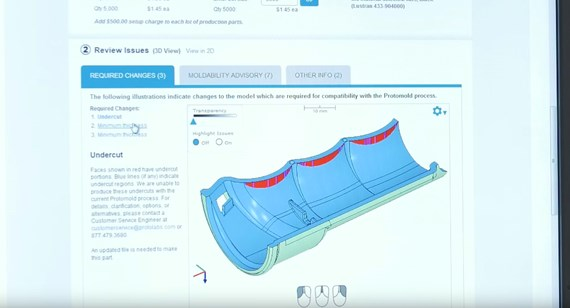
Free automated design for manufacturability (DFM) analysis is provided with every quote. This includes recommendations on how and where to modify part geometry to improve mechanical strength, reduce sink, adjust wall thicknesses, and other considerations that can improve cost, production and tool life. It’s an extremely valuable tool that can help refine a design into a more moldable part.
Finessing Surface Finish
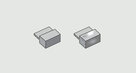
A common mistake made with injection-molded parts is calling out a better surface finish than is necessary for part function. A very smooth SPI-A2 (read: shiny) finish, for example, requires mold cavity surfaces to be hand-polished with diamond buff to 1-2 Ra. This drives up the cost of mold manufacturing and increases lead-time. The least expensive part finish is a non-cosmetic PM-F0, an as-machined surface that will probably show some tool marks. In between are two options such as a 10-12 Ra SPI-C1 finish, made using a 600 grit stone, or a PM-T1 bead-blast textured finish. Other finishes are available as well. Use the lowest-cost finish that is compatible with your application.
Don’t Be a Draft Dodger

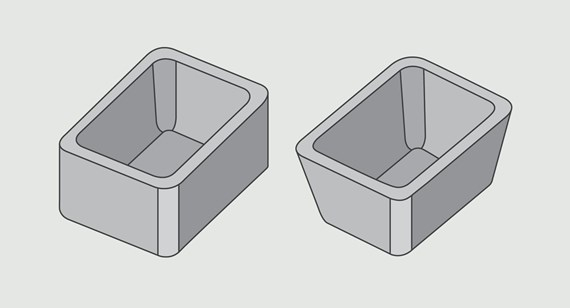
Draft is another aspect of molded products that designers familiar with machined or 3D printed parts may miss. Injection-molded parts need draft for the same reason that ice cubes aren’t true cubes. If an ice cube was cubical, you could never get the cube out of the tray. Ice cubes thus have tapered edges (or draft) and rounded edges, and so should injection-molded parts. Draft allows for easier ejection of the part.
A properly designed part carries at least 0.5 degrees of draft on all vertical faces, meaning those surfaces perpendicular to the parting line. If part design allows, 2 to 3 degrees is better. Where heavily textured or complex surfaces are used, 5 degrees or more may be necessary. The good news is that most CAD programs can easily take care of this for you during part design, as long as you understand how the part will be oriented in the mold. (Our applications engineers can help explain part orientation in the mold if you are uncertain.) If draft is missed in the initial design, our DFM analysis within your quote will highlight any features that may need it.
Scaling Wall Thickness Up and Down

Wall thickness is important. Imagine you’re designing a simple box. At first glance, thick walls might seem like a good way to keep the box’s contents safe. But the plastics used with injection molding are, well, plastic. Walls thicker than what is recommended for the particular thermoplastic family being used will be subject to warp and sink during cooling. A general rule of thumb for wall thickness is somewhere between 0.040 in. to 0.140 in. (1 to 3.5mm), applied consistently across the entire part.
Some plastics are more sensitive to wall thickness than others—where acetal and ABS plastics max out at around 0.12 in. thick (3mm), acrylic can go to 0.5 in. (12mm), polyurethane to 0.75 in. (18mm), and certain fiber-reinforced plastics to 1 in. (25mm) or more. Even so, designers should recognize that very thick cross-sections can increase the likelihood of cosmetic defects like a sink. For specific plastic types, see our recommended guidelines for wall thickness.
Keep an Eye on Radii

Since aluminum molds are machined using end mills, sharp internal corners are a concern. For that matter, sharp corners on any molded part tend to create stress and weaken structural integrity. As such, we recommend generous use of radii (rounded edges or vertexes) in part design. For the inside of a 4 in. by 6 in. by 2 in. box, for example, it might be best to plan on 0.25 in. (6mm) radiused corners for a strong part with improved moldability.
When Multiple Cavities Are a Good Thing
One of the beauties of injection molding is the opportunity to mold multiple parts in a single injection cycle. Once a part or parts have been designed, there is the potential option to employ either a multi-cavity mold or family mold. Multi-cavity molds involve more than one cavity cut into the mold to allow for multiple, identical parts to be formed in a single shot; family molds involve more than one cavity cut into the mold to allow for multiple, different parts to be formed in one shot.
Customers can use multi-cavity molds to simultaneously produce two or more part designs with minor iterations to quickly test different product designs in parallel. They are also a good option when quantities beyond the initial sample are required as they can help reduce cost per part. But bear in mind that while multi-cavity and family molds produce more parts per cycle, their use is highly dependent on geometry.
It’s best to test your design in single-cavity molds before committing to a multi-cavity mold. Additionally, if parts of different sizes and volumes are mixed in a family mold, it may cause difficulties in dialing in the injection process. Check with our customer service engineers for advice before setting up multi-cavity molds.
It’s a Material World
FacFox has dozens of thermoplastic resins in many different colors and additive filler options. Attributes such as durability, strength, chemical and thermal resistance, and others vary by plastic. If that’s not enough, liquid silicone rubber (LSR) injection molding, which requires less draft due to its flexible nature, is available. It uses a process similar to plastic injection molding, with comparable pricing and delivery.
Beyond Low-Volume Production
Paying attention to design consideration for quick-turn injection molding early in the product development process allows for efficiencies in prototype quality and turnaround time—benefits that ultimately help you iterate quickly and more reliably before market launch. And there’s added value when a product begins to grow to volumes in the hundreds of thousands. You now have a fully tested part design that can be produced easily and economically in steel tooling, drastically reducing your financial risks.