Take a look at an injection-molded toothbrush holder, a plastic gas can, or the silverware tray in the kitchen cabinet. Notice how the walls of these household items are all relatively uniform? This is one of the fundamental rules of plastic injection molding, and ignoring it can lead to sink, warp, and inaccurate or non-functional parts. Yet the functional requirements of the consumer, medical, aerospace, and industrial products often leave designers little consideration for the material flow and fill properties of plastic, both of which are at least partially determined by wall thickness.
To achieve uniform wall thickness, let’s start with the basics:
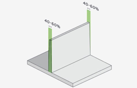
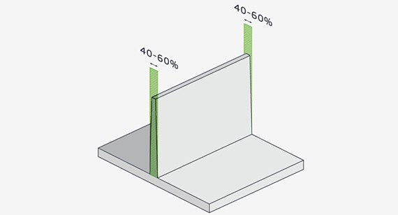
- Walls in any plastic-molded part should be no less than 40 to 60 percent that of adjacent walls, and all should fit within recommended thickness ranges for the selected material.
- Part geometries such as long unsupported spans, sharp internal corners, and poorly designed bosses (not the person in the corner office who signs paychecks), should be avoided, regardless of wall thickness.
- Use ribs for strengthening tall walls where needed.
- Sharp external corners are fine, but placing a radius on inside corners—part design permitting—makes them stronger and alleviates the stress that creates warp.
- Bosses should follow molding design guideline rules of properly designed walls of 40-60 percent of the surrounding area to avoid sink.
- Finally, follow recommendations on draft angles—1 degree of draft per 1 inch of cavity depth is a good rule of thumb—and keep draft consistent throughout the workpiece to prevent internal stresses that lead to warp and curl.
Choose Materials with Wall Thickness in Mind
One of the biggest considerations with wall thickness is which material to use for your project. With literally hundreds of materials to choose from, deciding on the right one can be challenging. You can view available resins grouped by a family with recommended wall thickness ranges along with detailed information on material properties, tensile and impact strength, and maximum operating temperatures online.
| MATERIAL | RECOMMENDED WALL THICKNESS |
|---|---|
| ABS | 0.045 in. – 0.140 in. |
| Acetal | 0.030 in. – 0.120 in. |
| Acrylic | 0.025 in. – 0.500 in. |
| Liquid crystal polymer | 0.030 in. – 0.120 in. |
| Long-fiber reinforced plastics | 0.075 in. – 1.000 in. |
| Nylon | 0.030 in. – 0.115 in. |
| Polycarbonate | 0.040 in. – 0.150 in. |
| Polyester | 0.025 in. – 0.125 in. |
| Polyethylene | 0.030 in. – 0.200 in. |
| Polyphenylene sulfide | 0.020 in. – 0.180 in. |
| Polypropylene | 0.025 in. – 0.150 in. |
| Polystyrene | 0.035 in. – 0.150 in. |
| Polyurethane | 0.080 in. – 0.750 in. |
Start by looking for which attributes are most important to the finished product:
- Does it need chemical or ultraviolet light (UV) resistance?
- Will the plastic be subjected to direct flame, or extreme temperatures?
- How strong must the part be, and will it need to flex under load?
- If the color is important, can the plastic be painted, or colorant added to the resin before injection?
- What about opacity? Some plastics have good optical properties, others not so much
- Will the product be used in an electromagnetic environment?
While all of these factors are being weighed, refer back to the website’s section on wall thickness. Obviously, materials only make good candidates if they can be molded to the dimensions and geometry needed for your project, while still meeting their engineering requirements. Once you’re close to selecting a material, give one of our customer service engineers a call. They can either advise you directly, or put you in touch with an expert at one of our material suppliers.
For example, nylon 6/6 flows well, is good for thin-walled parts, and has excellent impact resistance, but you might have rejected it because of its average strength and lack of resistance to heat. Adding glass-fiber filler to the resin not only makes the nylon much stronger, but far more heat resistant. Glass also reduces the chance of sink in thick sections, but may lead to warp in thin areas, depending on material flow during the molding process.
In some cases, you might be directed to a completely different material family:
- Polycarbonate is a common material used in designing optical components, but acrylic is often a better choice on thick parts, as it’s less likely to experience sink, voids, bubbles, and poor part detail.
- Optical-grade liquid silicone rubber (LSR) offers superior light transmission and product clarity, and allows designers to break the rules of thick and thin, even with very fine part features.
- A styrene-like material known as K-Resin is often a good substitute for ABS or polycarbonate in large structural components.
- Liquid crystal polymer (LCP) is another glass-filled material that’s strong but has the ability to “go thin” when needed.
Again, there are hundreds of materials and thousands of ways to adjust, blend, or fine-tune them to produce the desired results.
Clever Tweaks Can Help Strengthen Walls
Even if the right combination of material attributes can’t be found, don’t despair. Some clever edits to part geometry go a long way to alleviate internal stress and potential weakness produced by less than optimal wall thickness. Parts shaped like dumbbells or sewing bobbins are perfect candidates for coring, which eliminates large cross-sections of material similar to removing wedge-shaped slices of an apple, but the strong core is left in place. This is a great way to avoid sink, reduce material usage and make parts lighter but just as strong (possibly stronger). And parts like box lids that have tall, thin walls can be reinforced with gussets, so long as the relative wall thickness of the supporting material follows the 40 to 60 percent rules mentioned previously. This also eliminates the chance of shadowing, which occurs when one section of the part cools down faster than others.
Design for Manufacturability Offers Feedback
Once you receive your part quote, be sure to review the accompanying design for manufacturability (DFM) analysis, which provides feedback to improve the moldability of your part. Overly thick or thin areas will be color-coded based on nominal wall thickness, along with recommendations on changes to draft angles. Parting lines, ejector and gate locations, undercuts, side-actions, and the need for hand-loaded inserts are displayed as well. If deemed necessary, flow analysis can be performed, to analyze pressure points around gate areas, and to identify potential knit lines. As always, feel free to us at info@facfox.com if questions or concerns emerge.