Introduction
Living hinges are a simple, low-cost method of connecting two rigid plastic parts with a flexible joint. This article will discuss the advantages of using living hinges and present design rules and material recommendations when using 3D Printing to produce living hinges.
What are living hinges?
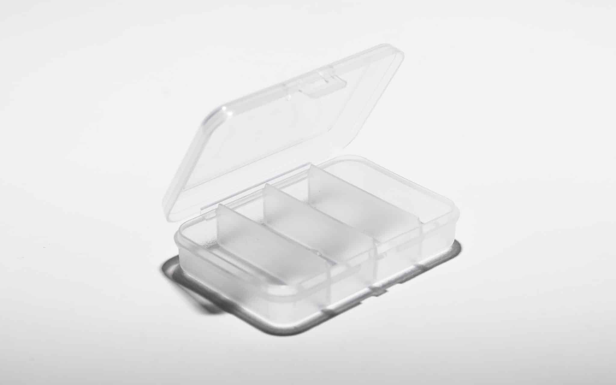
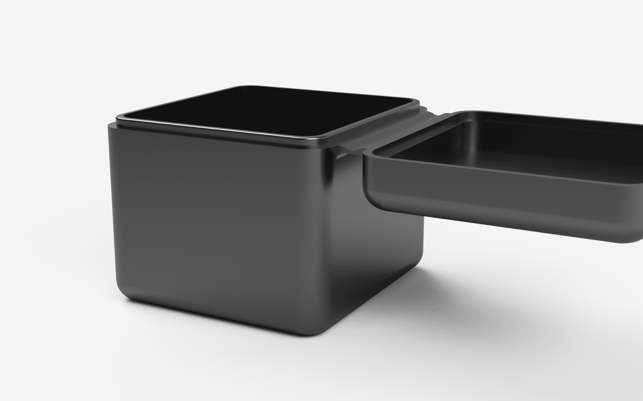
A living hinge is a thin flexible web of plastic that connects two or more rigid sections. Typically the larger rigid sections and the living hinge will be made of one continuous piece of plastic. The low cost and simplicity of living hinges make them a popular option for many applications. They can be found on almost every commercial product: from drink and shampoo bottles to workshop storage containers and food packaging. Living hinges and the connected rigid sections are manufactured almost exclusively as one part via injection molding.
Advantages of living hinges
Living hinges are an effective solution when two rigid sections need to be joined together. Some of the advantages of a living hinge include:
- Low Cost – Because of their simplicity, living hinges are usually a much cheaper alternative compared to other hinge types.
- Durability – Living hinges are specifically designed to be opened repeatedly. They experience very little friction when opened and closed and this typically results in a long lifespan.
- Reduced inventory – Living hinges are integrated into a part eliminating the need for extra components.
- Appearance – Compared to other connection options (assembled hinges, snap-fit connections, etc), living hinges are an aesthetically pleasing and non-obtrusive connection solution.
The main limitation of living hinges centers around their inability to bear any load.
3D printed living hinges
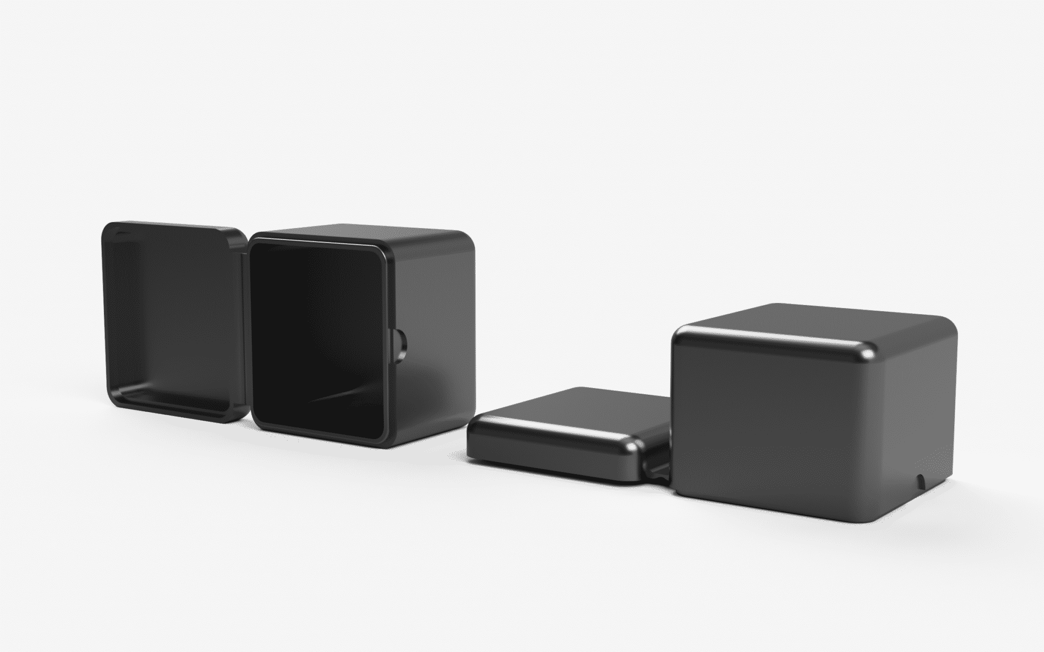
While injection molded living hinges are designed to withstand thousands of cycles without breaking, the nature of 3D printed parts (usually anisotropic, brittle, layer-by-layer constructions) means that 3D printed living hinges are typically used for prototyping or proof-of-concept models where a small number of cycles are needed. This makes 3D printed living hinges best suited for the verification of a design before needing to invest in expensive injection molding tooling.
The main benefits of 3D printing a living hinge are:
- No need for expensive tooling.
- The design does not need to incorporate features essential to injection molded parts such as gates, runners, or sprues.
- Designs can easily be altered and iterated to achieve an optimal design.
- 3D printing is able to produce parts quickly further accelerating the design process.
Designing living hinges for 3D printing
As with other 3D printed features, performance will vary based on design, material, printer calibrations, and layer thickness. Because of this, creating the optimal living hinge for a specific design and technology is often an iterative process. This section offers several design recommendations that can be used as a starting point.
Print direction
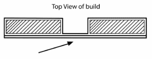
Due to the additive, layer-by-layer nature of 3D printing the parts that are produced are typically anisotropic (especially when printing with FDM). To ensure the performance of a living hinge, parts should be orientated so that the width of the hinge rather than the length is built up one layer at a time (the central axis of the hinge should be orientated in the Z-direction). This will often mean printing the part in the vertical build direction, as shown in the image below.
Hinge geometry
For most prototyping applications, simply printing a thin strip of material is adequate if the hinge is only required to be functional for a few cycles. If a greater number of cycles is required the hinge geometry should be optimized.
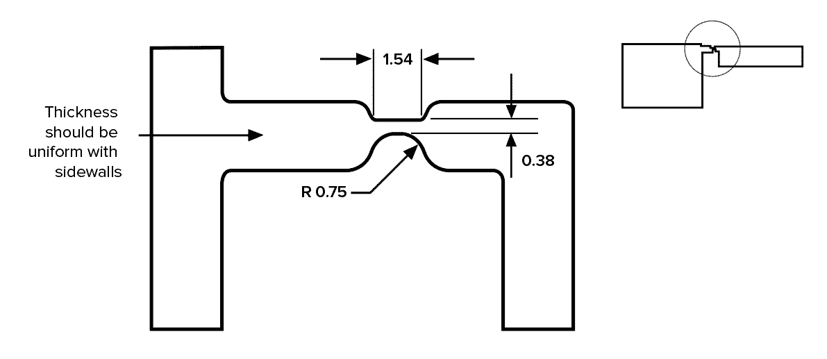
As a hinge is closed, it is subjected to bending: the outer surface is placed under tension (and stretches), while the inner surface is compressed. To account for this, a good living hinge design should have a long, curved length on the outer surface and a short inner surface. The image below illustrates a standard injection molded living hinge with dimensions in mm.
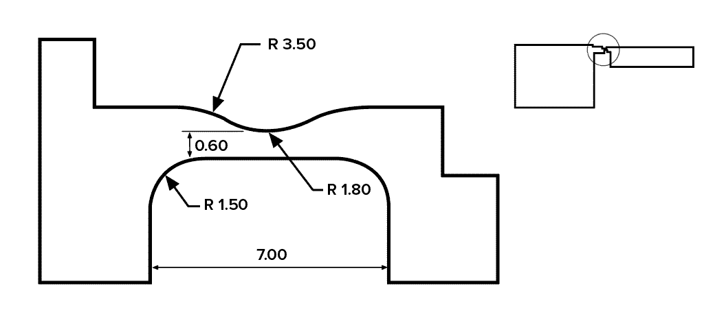
For 3D printing, more material and a stiffer hinge is generally required to improve the number of cycles before failure. Note though that increasing the thickness of the hinge will also increase the tensile stresses that the outer surface is subjected to. The figure below shows the dimensions of an FDM printed living hinge that achieved 25-30 cycles before failure (all dimensions are in mm).
Design by technology
The materials and processes that each 3D printing technology produce parts can vary significantly. Because of this, different design rules often apply to each technology. The 3D printing processes listed below are the most suitable for creating living hinges.
| Technology | |
|---|---|
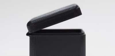
| Fused Deposition Modeling (FDM) | The optimal design for a living hinge produced via FDM is to try and print the hinge with a single strand of thermoplastic integrated into the rigid sections of the build (as shown in the image below).
 This may mean that the part will be printed vertically, resulting in a large amount of required support structure. This will add to the cost and build time of the part. Some dual extrusion FDM printers offer the option to print the hinge section in a secondary flexible material (like TPU) which will further improve hinge performance and the number of cycles before failure. Build orientation is still important for these materials. Recommended hinge specifications: Minimum of 2 layer thicknesses with 0.4 – 0.8mm recommended |
| Selective Laser Sintering (SLS) | While SLS parts are less susceptible to delamination of layers when compared to FDM, the build direction is still an important factor when designing living hinges. SLS parts are usually printed in nylon (PA 12) and the produced hinges typically last around 30 – 50 cycles before failure. Recommended hinge specifications: 0.3 – 0.8mm thick and a minimum of 5 mm in length |
| Material Jetting | Parts produced via Material Jetting are typically more isotropic than either FDM or SLS parts. The material jetted parts are very smooth and are often aesthetically comparable to injection molded parts. The general rigid photopolymers used in Material Jetting are brittle and unsuitable for prototypes, where more than 10 cycles are required. One of the major advantages of Material Jetting though is the ability to produce multi-material prints. By printing the hinge section in a flexible material a living hinge design can be produced that will last a large number of cycles. Recommended hinge specifications: 0.4 – 0.8mm thick |
Post-processing
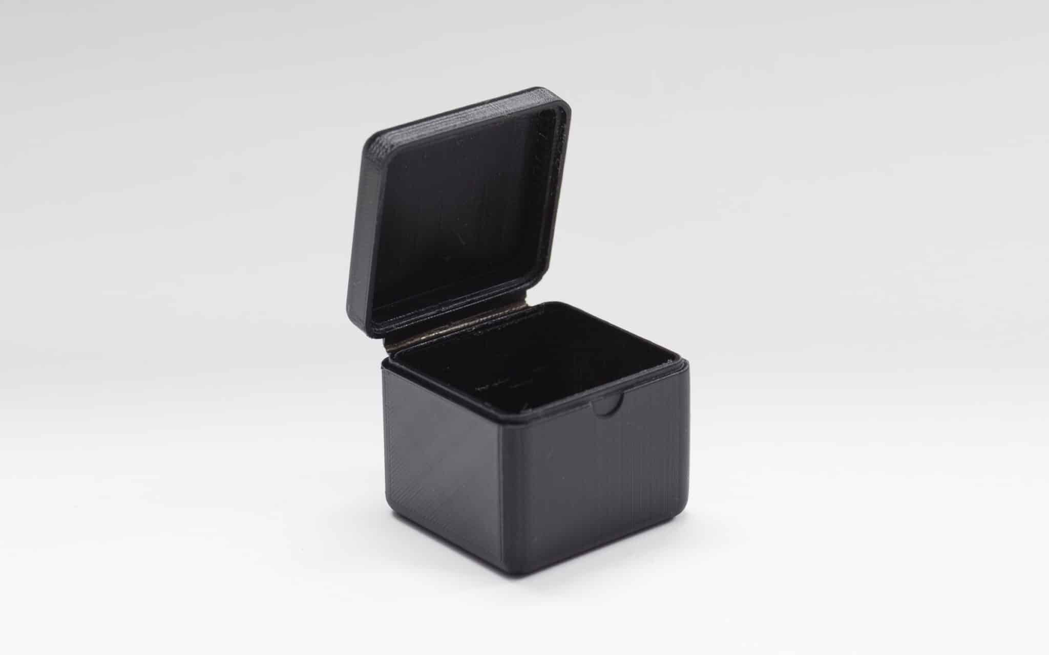
Living hinges can be annealed after printing to increase the number of cycles before failure. This is can be achieved by heating up the hinge (for example by gently running a flame over the hinge until it reaches a flexible state without melting), working it back and forth for several cycles at that elevated temperature, and then leaving it in the closed position to cool down.
The effectiveness of this process will depend greatly on the material and the geometry of the hinge. For the example shown in the images above (which is printed with FDM), annealing greatly increased the number of cycles the hinge could withstand before failure.
Recommended materials
Injection-molded living hinges are made almost exclusively from polyethylene (PE) and polypropylene (PP) plastics. Both materials are flexible and soft with a relatively low melting point.
For 3D printed living hinges, materials that have a high elongation at break and good tear resistance are most suitable. The recommended materials for each process described above are summarised in the table below.
| Technology | Recommended material |
|---|---|
| FDM | Single material: Nylon 12
Multi-material: PLA or ABS for the body, and flexible TPU for the hinge |
| SLS | Nylon (PA 12 or PA 11) |
| Material Jetting | Single material: Durable resin (PP-like)
Multi-material: Durable resin (PP-like) or Digital ABS for the body and flexible Rubber-like resin for the hinge |
Curious about the cost of prototyping with 3D printing?
Rules of thumb
- Living hinges made via 3D printing are best suited for proof of concept designs before investing in expensive injection mold tooling.
- Living hinge geometry should have a long outer surface path and a short internal path.
- Dimensions and materials for the best suited 3D printing technologies for producing living hinges are summarised in the table below:
| Technology | Dimensions | Material |
|---|---|---|
| FDM | 0.4 – 0.6 mm | Nylon 12 |
| SLS | 0.3 – 0.8 mm thick and a minimum of 5 mm in length | PA 12 or PA 11 |
| Material Jetting | 0.4 – 0.8 mm thick | Durable resin (PP-like) and/or flexible Rubber-like resin |