DMLS 3D printing is a revolutionary technology that can create complex and functional metal parts from digital models. However, metal 3D printing is not as simple as plastic 3D printing. There are many factors that you need to consider before you start your metal 3D printing project.
In this post, we will share with you some important tips and precautions for metal 3D printing based on our experience and expertise.
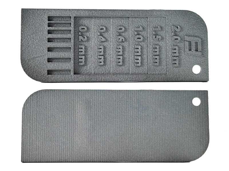
Minimum Wall Thickness
We could not guarantee that walls thinner than 0.5 mm can be printed successfully. Thin walls may collapse or deform during sintering due to thermal stress and shrinkage.
Additionally, if you want additional finishing like polishing, brushing, mirror polishing, or other advanced finishing effects on your parts, you should design your parts with even thicker walls. This is because these finishing processes may remove some material from the surface of the parts and reduce their thickness further.
The recommend minimum wall thickness for different finishing options is as follows:
- Polishing: 0.6 mm
- Brushing: 1.2 mm
- Mirror polishing: 1.2 mm
- Other advanced finishing effects: 1.2 mm
You can also refer to this illustration of DMLS design rules. The blue/teal color represents micron resolution (MR), green is high resolution (HR), and orange is normal resolution (NR). Also, the minimum channel and minimum Z dimensions apply to both NR and HR.

Minimum Clearance for Assemblies
Additionally, if you want your assembly parts to fit together smoothly and accurately, you should design them with enough clearance between them. The minimum clearance for DMLS 3D printed assembly parts is 0.15 mm on each side.
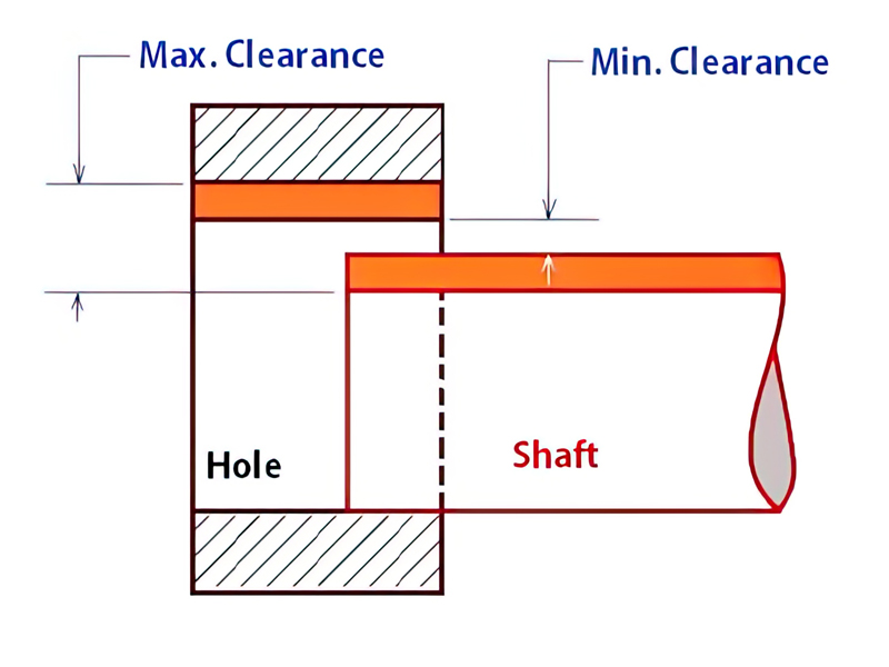
Clearance is the gap or space between two mating surfaces of the parts. It allows for some tolerance and flexibility during assembly.
This means that if you have two parts that need to be inserted into each other (such as a pin and a hole), the diameter of the pin should be 0.3 mm smaller than the diameter of the hole (0.15 mm on each side).
Similarly, if you have two parts that need to slide along each other (such as a rail and a groove), the width of the rail should be 0.3 mm smaller than the width of the groove (0.15 mm on each side).
Allowance for Precise Assemblies
For parts that require high precision for local assembly, please leave some machining allowance in advance and then use CNC machining to achieve a better fit.
The local assembly is a type of assembly where two or more parts are joined together at a specific location or feature on the part. Local assembly requires high precision and accuracy to ensure that the parts fit together perfectly and function properly.
Therefore, we recommend that you leave some machining allowance in advance and then use secondary machining to achieve a better fit. Machining allowance is the extra material that you add to the part during design or printing to allow for some removal or adjustment later on. We can use tools such as drills, mills, lathes, etc. to refine or modify the part after printing.
For example, if you need a bearing hole with a diameter of 10 mm and a tolerance of +/- 0.01 mm on your part, you can design and print the hole with a diameter of 10.1 mm (0.1 mm machining allowance) and then use a drill to reduce it to 10 mm (+/- 0.01 mm tolerance) after printing.
By leaving some machining allowance in advance and using secondary machining later on, you can achieve higher precision and accuracy for local assembly than by relying solely on DMLS 3D printing.
Finishing of DMLS 3D Printing
The average surface roughness (Ra) of DMLS 3D printed parts is about 3.2-6.3 microns, which is much higher than the typical Ra of machined parts (0.4-1.6 microns).
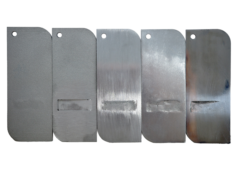
If you need a smoother surface finish for your parts, you may need additional post processes such as machining, polishing, sandblasting or coating. These post processes can improve the surface quality and appearance of your parts, as well as reduce the friction and wear between moving parts. However, they may also increase the cost and lead time of your order.
Weakness of DMLS 3D Printing
The sintering process may cause some elongated, thin-walled, shell-like structures to deform due to thermal stresses and shrinkage.
DMLS 3D printed parts require high-temperature sintering after printing to increase their strength and density. Therefore, if your design has such features, you may want to consider modifying them or choosing a different manufacturing method.
DMLS 3D Printing vs. CNC Milling
Metal 3D printing has an advantage in creating complex structures, but its accuracy and surface quality are inferior to machining.
The laser beam diameter and the metal powder size affect the resolution and surface roughness of the printed parts. Moreover, DMLS 3D printed parts may have internal porosity and residual stresses that affect their mechanical properties.
The accuracy of metal 3D printed parts is not as high as CNC machining. The accuracy of metal 3D printed parts is about +/-0.1 mm or +/-0.2%, whichever is larger. This means that the actual dimensions of your parts may deviate from the design dimensions by up to 0.1 mm or 0.2% in any direction.
Therefore, if your design requires high precision and a smooth finish, you may need additional post-processing steps such as CNC machining or polishing. To know more, please read this post: FacFox CNC Machining vs 3D Printing Services: Compare and Choose the Better One for You.
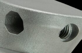
Threading
We recommend using tapping instead of direct 3D printing for creating threads on your metal parts. This is because direct 3D printing may result in poor quality or inaccurate threads due to the nature of the metal powder and the sintering process.
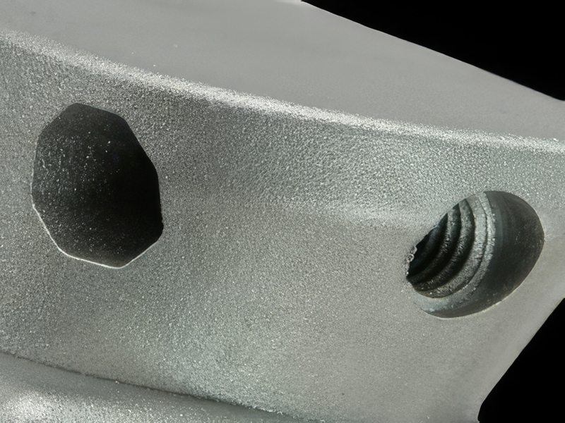
Metal powder is the raw material used for 3D printing metal parts. It consists of tiny particles of metal that are fused together by heat and pressure. Sintering is the final step of 3D printing where the metal powder is heated to a high temperature below its melting point to bond the particles together.
During sintering, some shrinkage and distortion may occur due to thermal expansion and contraction. This may affect the shape and size of the threads and make them uneven or misaligned. Additionally, some residual powder may remain inside or outside the threads and make them rough or clogged.
Therefore, tapping through CNC milling is a more reliable and precise method for creating threads on your metal parts. It ensures that the threads have smooth surfaces and accurate dimensions that match the standard specifications.
Post-processing with Conventional Methods
Metal 3D printed parts can be further processed by conventional methods such as machining, welding, heat treatment, etc.
DMLS 3D printed parts may not meet all your requirements in terms of surface quality, accuracy, strength, or functionality. Therefore, you may want to further process your parts by conventional methods such as machining, welding, heat treatment, etc.
CNC Machining can improve the surface quality and accuracy of your parts by removing excess material and unwanted features such as support structures or burrs. Machining can also create additional features such as threads, holes or slots that are difficult or impossible to print.
Welding can join multiple DMLS 3D-printed parts together to form larger or more complex assemblies. Welding can also repair any defects or cracks in your parts that may occur during printing or sintering.
Heat treatment can modify the microstructure and mechanical properties of your parts by applying controlled heating and cooling cycles. Heat treatment can increase the strength, hardness, or ductility of your parts depending on the type and duration of the treatment.
These conventional methods can enhance the performance and functionality of your DMLS 3D printed parts and make them suitable for various applications. However, they may also increase the cost and lead time of your order and require additional design considerations.
Assembling Service
If you want us to assemble the parts for you, you need to send us an assembly drawing before shipping.
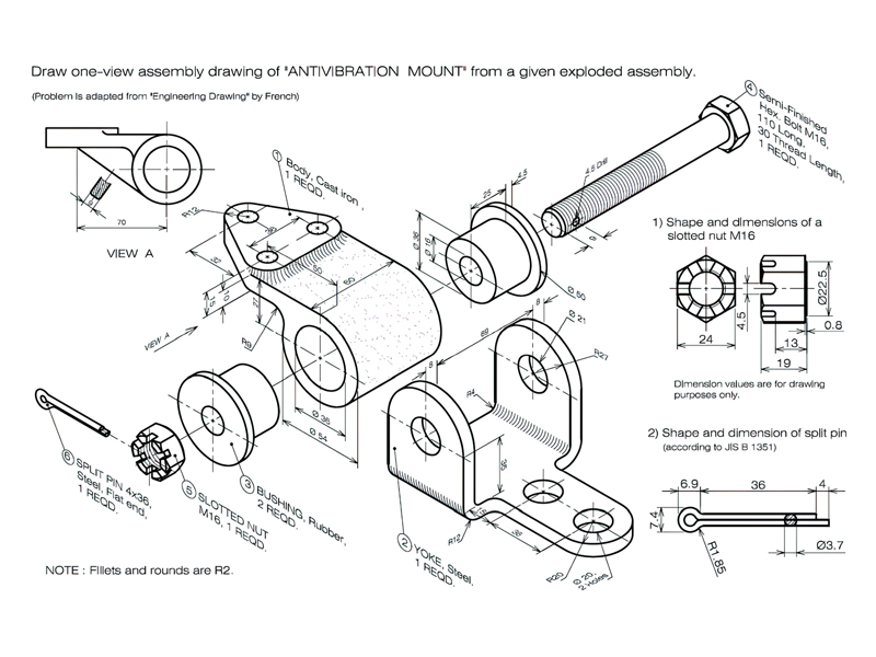
If you do not send us an assembly drawing before shipping, we are not responsible for assembling the parts. You will receive the parts as they are printed and you will have to assemble them yourself.
An assembly drawing is a diagram that shows how the parts should be arranged and connected together. It should include dimensions, labels, annotations and instructions for the assembly process.
We hope this post has given you some useful information about metal 3D printing.
If you have any questions or want to start your own metal 3D printing project with us,
please contact us via info@facfox.com today!😊