To skilled sheet metal designers, the world is flat. Knowing that every part they make starts out as a thin, flat piece of metal certainly affects how they design their parts. Where it goes from there is determined by the designer’s ability to envision that part after fabrication. It has to make sense as a sheet, while also functioning in three dimensions. That’s the challenge.
Many designers prefer to work initially from a 3D design and then make the transition to sheet metal to create a flat design. For example, in SolidWorks, there are two tools to accomplish this. If you start with a solid 3D object, the Convert to Sheet Metal command is your friend. If you already have a formed part with uniform thickness, use Unfold to ensure that your part is sheet metal worthy. Both will get you partially there, but you still have to consider other elements of your part and how to get it to behave like a sheet metal flat. This design tip presumes that you’re starting from a solid 3D object, as many designers do. Here are some basic rules to help get you started.
Comparing Sheet Metal Design Methods: Flat vs. Solid

Let’s say you want to build a cube without a top. If you had designed it as a flat part, it would initially look more like a plus sign, with four outer squares surrounding a square in the center (see animation). The four outer squares would be folded upward to form the sides of the open-top box. All of those loose sides can be welded together later.
If you design a solid 3D cube, Convert to Sheet Metal gets you where you want to go. Start by modeling a cube that has uniform material thickness—it is sheet metal, after all. Doing this will save you some time and aggravation later. When you use Convert to Sheet Metal, you’ll get a manufacturable sheet metal part. Easy, right? Needless to say, not all designs are this simple because of the nature of sheet metal.
Rips and Seams in Sheet Metal
The great thing about the Convert to Sheet Metal command is that rips and seams are introduced into the model automatically. Rips are the processes that allow you to create seams, and are typically needed when designing certain kinds of formed parts. Without seams, you wouldn’t have areas for the metal to unfold.
As you can imagine, when the flat part is put on a press brake and formed into a box shape, the edges between the sides will be parallel, but not connected. Your designs can indicate that all of the sides be welded together, to return the form to a solid box.
Bend Radii on Sheet Metal Parts
When you bend sheet metal in a press brake, say to make a 90-degree corner for our box, you don’t get a straight or sharp interior within that perpendicular bend. The tooling actually creates a slight curve at the exterior and interior bend point called a bend radius. Your designs should take this into account because it might affect the geometry of your part. The standard interior bend radius is 0.030 in. (0.762mm). Forming all the bends with the same radius is always a good idea. It’s important to note that any time your design requires multiple setups, it could increase your part price and lead times. Adding those bend radius specifications in the model can also improve your lead times.
Bend Relief in Sheet Metal Design
Here’s the tricky thing about that open-top box we’re building. If you try to bend those sides up on a press brake, the surrounding metal will deform because you haven’t designed in bend relief. It’s nothing more than two small incisions, located on either side of a bend feature. Remember that each soon-to-be vertical side of the box is essentially a flange and has to be able to move independently of the others.
Before unfolding your part in your design program, make small cuts in the corners where two sides meet. They should be at least 0.030 in. wide and locate them at least 0.015 in. (0.381mm) past the end of the bend radius on either side of the bend on your part. This will allow the metal to bend freely and the part to form properly.
You’re probably thinking that this will create a small hole in that corner, and you’re right. The good news is that the area impacted is very small. Welding will take care of that, if needed, to make your part stronger in that location.
Crashing Features in Sheet Metal Designs
It’s not just a great name for a punk band, it’s a basic course in physics. Quantum mechanics says that you can’t have the same particle in two places at once. In our box example, imagine that we incorporated a hole on one side with four flanges bent outward from the hole. The flanges are the same size as the hole. As you can guess, that won’t work. Once you’ve designed a flange for a certain area, that metal is no longer available to be used elsewhere. Instead, you will want to create a second part (or multiple parts) that make up the box surrounding the hole. That one should be entirely separate from your primary part.
WARNING: Some design programs will allow you to create parts with no thickness. It’s up to you to catch this issue in the unfolding phase or you may hear from your manufacturer, delaying your part.
Beware of Non-Uniform Thickness
This one sounds pretty sensible, and that’s because it is. Your designs must reflect the reality that sheet metal has a single thickness. If your sheet metal is 0.100 in. (2.54mm) thick, the entire part must have that thickness, too. Keep an eye out for differences such as this that will prevent your part from unfolding properly.
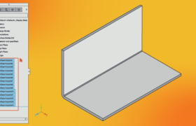
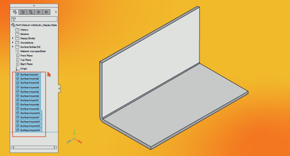
Surface Imports for Sheet Metal
Here’s a tricky one. It’s possible to design parts that are all surfaces. They look like solid parts, but are actually hollow and the surfaces have no material thickness. In the example here, this part actually consists of 10 surfaces—all six edges plus the four flat sides—each with a thickness of zero. So, this looks good visually but it won’t unfold to sheet metal. The best solution is to always start with a solid body and maintain a uniform thickness throughout the whole design.
Sheet Metal Feature Locations
With all sheet metal design, you have to consider where you place features relative to each other. What looks good as a solid part may not translate well, or even be possible, unfolded as a flat. So, it’s important to visualize the fabrication process in your mind before assuming that your design will make sense. For example, if you want a hole near a bend and you locate these two features too close to one another, you would likely end up with a deformed part. The press brake will not be able to form the metal smoothly if there isn’t a solid area where the forming tools are used.
The good news is that there are some simple, easy-to-follow rules you can use. Once you’ve determined your material thickness, always aim to keep a distance of four times that thickness in mind when locating holes. Also, make sure that the length of all hems and flanges is at least four times the material thickness. Using the 4T Rule of Thumb, you can avoid part failure during manufacturing.
Ultimately, designers who are more comfortable modeling 3D solid objects can still create manufacturable sheet metal designs. It just takes a few extra steps and the ability to flatten your perspective. Check out our webinar, How to Unfold Sheet Metal Components for a more detailed exploration of the topic.
For additional help, feel free to contact a FacFox applications engineer at info@facfox.com. To get your next design project started today, simply upload a 3D CAD model for an interactive quote within hours.