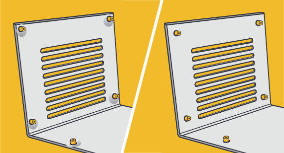
Light, strong sheet metal components are often fabricated and assembled into structures and products of all types and sizes: buildings, automotive parts, home appliances, airplane components, chassis, cabinets, cases, electrical enclosures, and so on. Your hardware choices are pivotal to final parts. They are often used to connect and bolster components or provide threads for assembly because sheet metal is thin, so it is difficult or impossible to thread holes in the metal. This is why these connectors play a prime role, essentially becoming part of the sheet metal and providing a more robust thread or connection. Considering hardware specifications should be an important step in your design process.
This tip looks at four design elements to consider when incorporating hardware into sheet metal part design:
- Determining material compatibility of sheet metal and hardware
- Choosing the right connectors
- Positioning the placement of hardware
- Timing the installation of hardware
Determining Material Compatibility of Sheet Metal and Hardware

A key early step in integrating nuts, pins, studs, and other connectors into your part design is to consider sheet metal and hardware compatibility—selecting the connector material to make sure it works with the type of sheet metal being used. This is where material hardness comes into play. In other words, how hard is your hardware?
The connector must have a hardness that is equal to or greater than the sheet metal material into which it is inserted, otherwise the connector can be damaged in the insertion process or when parts are connected. If the sheet metal material is harder than the hardware material, the connector or fastener won’t flow and create the clinching action required for a secure installation. A secondary consideration in choosing the type of material for your connector may be your intended finishing process for your part, if you wish to have the same finish on your connector.
Choosing the Right Connectors
Identify the class of PEM (or other) fasteners you need based on function. Typically, the choices for sheet metal applications are:
- Nuts of various sorts into which you’ll insert screws
- Studs in several categories onto which a nut can be fastened
- Threaded and unthreaded standoffs to provide spacing between connected parts
In your designs, standard in-stock hardware parts are definitely the way to go. We stock most of the hardware you are likely to need. By designing around in-stock parts, you can shorten your lead time.
You’ll also want to determine the thread you’ll be using for the connection and choose the appropriate thread code if you are using a PEM connector.
Available Sheet Metal Hardware by Type
Self-Clinching Nuts
| SS-M5-2 | SP-M3-2 | SMPS-M25 | S-M3-0 | S-632-3 | CLSS-M5-2 | CLS-M3-0 | CLS-440-1 |
| SS-M5-1 | SP-M3-1 | SMPS-440 | SL-M5-2 | S-632-2 | CLSS-032-3 | CLS-M2-2 | CLS-440-0 |
| SS-032-3 | SP-M3-0 | SMPS-256 | SL-M4-2 | S-632-1 | CLSS-032-2 | CLS-832-3 | CLS-0420-3 |
| SS-032-2 | SP-832-2 | S-M6-2 | SL-M3-2 | S-632-0 | CLSS-032-1 | CLS-832-2 | CLS-0420-2 |
| SP-M6-2 | SP-632-2 | S-M6-1 | SL-M3-1 | S-440-3 | CLS-M6-2 | CLS-832-1 | CLS-0420-1 |
| SP-M6-1 | SP-632-1 | S-M4-2 | SL-832-2 | S-440-2 | CLS-M6-1 | CLS-632-3 | CLA-M4-2 |
| SP-M5-2 | SP-0616-1 | S-M4-1 | SL-632-2 | S-440-1 | CLS-M4-2 | CLS-632-2 | CLA-M3-2 |
| SP-M5-1 | SP-0420-2 | S-M4-0 | S-832-3 | S-440-0 | CLS-M4-1 | CLS-632-1 | CLA-440-1 |
| SP-M5-0 | SP-032-2 | S-M3-2 | S-832-2 | S-0420-2 | CLS-M3-2 | CLS-440-3 | |
| SP-M4-2 | SMPS-M3 | S-M3-1 | S-832-1 | S-0420-1 | CLS-M3-1 | CLS-440-2 |
Self-Clinching Standoffs
| TSOS-M25-1400 | SOSG-6440-8 | SOS-632-12 | SOS-440-10 | SO4-440-4 | BSOS-M3-8 | BSOS-440-12 |
| BSO-M3-6 | TSOS-256-187 | SOSG-35M3-6 | SOS-440-8 | SOS-35M3-12 | SO-440-6 | BSOS-M3-6 |
| BSOS-440-10 | BSO-M3-12 | TSOS-256-090 | SOS-8169-6 | SOS-440-6 | SOS-032-4 | SO-35M3-6 |
| BSOS-M3-14 | BSOS-35M3-8 | BSO-632-32 | TSO-256-187 | SOS-6440-8 | SOS-440-16 | SO-M35-6 |
| MSO4-M2-3 | BSOS-M3-12 | BSOS-35M3-12 | BSO-632-10 | SOS-M4-6 | SOS-6440-6 | SOS-440-14 |
| SO-632-8 | DSOS-440-250 | BSOS-M3-10 | BSO-M3-8 | BSO4-M3-6 | SOS-M3-6 | SOS-632-8 |
| SOS-440-12 | SO-632-6 | BSOS-M4-8 | BSOS-632-10 | BSO-M3-8 | BSO-032-10 |
Flush-Head Stud
| FHS-M5-15 | FHS-M3-8 | FHS-632-8 | FHS-440-6 | FH-M8-18 | FH-M4-12 | FH-632-5 |
| FHS-M5-12 | FHS-M3-10 | FHS-632-6 | FHS-440-5 | FH-M6-18 | FH-M4-10 | FH-440-8 |
| FHS-M4-8 | FHS-832-8 | FHS-632-4 | FHS-440-12 | FH-M5-12 | FHA-032-8 | FH-0518-12 |
| FHS-M4-25 | FHS-832-6 | FHS-632-20 | FHS-440-10 | FH-M5-10 | FH-832-16 | FH-0420-12 |
| FHS-M4-10 | FHS-832-10 | FHS-440-8 | FHS-032-8 | FH-M4-8 | FH-632-6 | FH-032-8 |
Miniature Self-Clinching Nuts
FEX-M3FEX-440FEO-440-MDFE-440-MD
Self-Clinching Flush Nuts
| F-M4-2 | F-M4-1 | F-M3-2 | F-M3-1 | F-832-1 | F-632-1 | F-440-1 |
Flush-Head Pin
| TPS-4MM-10 | TPS-3MM-8 | TPS-187-6 |
Self-Clinching Blind Fastener
| BS-M6-1 | B6-632-1 | BS-440-1 |
Thin Sheet Non-Flush Stud
| TFHS-M3-8 | TFHS-632-4 |
Self-Clinching Lock Nut
| LKS-M3-1MD |
Self-Clinching Micro Pin
| MPP-2MM-4 |

Positioning the Placement of Hardware
When designing your sheet metal part, where you position the connectors or fasteners is also a key decision in order to ensure that the placement won’t affect the structural integrity of your part or compromise the hardware’s installation. To maintain this integrity—and for ease of insertion—connectors must maintain a minimum distance from the edges of parts, from bends, and from other connectors. If they are installed too close to the edge, the material will displace and bulge. If it is too close to a feature like a bend there will be difficulty ensuring the hardware is installed straight. Accordingly, placement is an important piece to not overlook as you design, and will help ensure that your part will be manufacturable and hold up over time.
This location issue also comes into play when placing holes and slots certain distances from part edges, folds, and bends. One consideration on placing holes for PEM connectors is the size of the arbor press used to install the holes. The installation tools are typically 0.5 inches in diameter. Holes must be positioned such that the press won’t impinge, as mentioned, on a fold or bend when installing the connector. In other words, if the installation tool can’t be flush with the part, we can’t install to manufacturer specifications.
Additionally, if you are using PEM hardware, you’ll also need to keep in mind the shank depth of the desired connector. This is specific to the thickness of the sheet metal into which the connector will be inserted. For best performance, it is recommended you choose the maximum shank length for your sheet metal thickness.
Timing the Installation of Hardware
Finally, depending on the kind of plating the part will receive after fabrication, and the type of material it’s made of, the insert or connector (whatever it might be) may need to be installed before or after the post-processing operation. It is recommended you check with a FacFox applications engineer regarding this issue of hardware installation timing.
Hardware is Tricky
Ultimately, to effectively use hardware—whether they are PEM fasteners or other connectors—you’ll need to make several key decisions. These include material compatibility, selecting the right connectors for your part, location of the connectors, and the timing of hardware installation.
For additional help, feel free to contact a FacFox applications engineer at info@facfox.com. To get your next design project started today, simply upload a 3D CAD model for an interactive quote within hours.
| NAVIGATING PEM HARDWARE |
|---|
Penn Engineering provides detailed descriptions and specifications regarding PEM hardware, but can be a bit of a navigation challenge. Some tips to keep in mind:
|
