Additive manufacturing imposes inherent manufacturing and design challenges that impact the dimensions and tolerances that you can (or cannot) achieve on an “as built” part.
Designers spend countless hours perfecting the curves and contours of their 3D models in CAD for both aesthetic and functional reasons. Unfortunately, if you have 3D printed anything before, you know that the geometry you print will not be the same as the model you made in CAD. Why is that?
First, most 3D models need to be exported as STL files from their native CAD software in order to be read into build-preparation software such as Materialise Magics and Autodesk Netfabb before additive manufacturing (AM) can take place. During this file export, the 3D model’s edges, contours, curved surfaces and more are approximated by a bunch of triangles in a process called tessellation. So, circles are not perfect circles anymore; they are approximations formed by a series of straight lines—the edges of the triangles used in the tessellation (see Figure 2).
So why not make the triangles smaller (and smaller) to improve the approximation? You can do that, but that increases the likelihood of errors in the STL file. Errors can occur from numerical precision, round-off error, misaligned vertices and more. Most STL files have to be checked and fixed before preparing them for 3D printing. Also, as the triangles get smaller, the file size will quickly grow into the GB range, especially for complex, organic shapes and lattices, making the build process painstakingly slow.
The second issue you will face deals with the realities of layer-by-layer fabrication when using AM. For horizontal and vertical surfaces, the layering, or “staircase” effect, is not an issue. However, slanted surfaces, curved shapes, fillets, holes and others must be carefully considered to minimize the impact of the staircasing that is inherent in the AM process. We mostly ignored this when AM was used for prototypes and visual aids, but now that we want to manufacture functional parts with AM, the layering matters.
So why not reduce the layer thickness and minimize the height of the stairsteps? This is certainly a possibility, but reducing the layer height means building more layers, which will drive up build time. Recoating a single layer with new-powder feedstock can easily take 7 to 8 seconds, which does not sound like much until you multiple it by the thousands upon thousands of layers that may be needed for a build. For example, a 1-inch-tall part will be sliced into 1,270 layers when building with a 20-micron layer thickness.
So why not reorient the geometry so that sloped surfaces become vertical or horizontal? That is certainly possible, but then surfaces that were horizontal or vertical will likely become slanted, and you have the same issue as before. Depending on the overhang angle, you might also need to add support structures, which will leave additional material behind when removed. Needless to say, optimizing the part’s build orientation to minimize the impact of staircasing and tessellation is an important step when designing for AM.
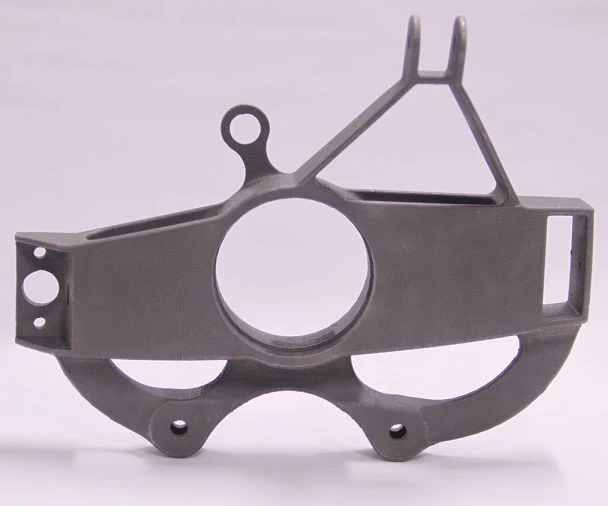
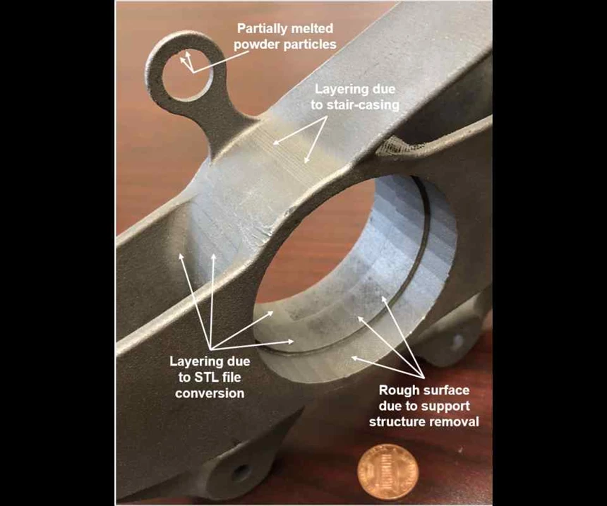
Finally, despite your best efforts optimizing the build orientation, you still have to contend with the fact that your part is being built by melting small, metal-powder particles with a laser when using powder-bed fusion. This process does not leave clear/crisp edges on a part, and partially melted powder particles can stick to the sides of the part, making surfaces even rougher. As an example, Figure 3 shows an Inconel 718 part designed by my colleagues Professors Ed De Meter and Amine Lehtihet for fabrication on an EOS M280 laser-powder-bed fusion system in the orientation shown. Inconel 718 parts tend to have some of the smoothest surfaces of the AM parts we have made.
So, what does this mean for you? Well, if you are making AM parts, then you need be aware of the inherent manufacturing and design challenges that impact the dimensions and tolerances that you can (or cannot) achieve on an “as built” part. If you are machining AM parts, then you will want to make sure that the designer has added sufficient machining allowances to mitigate the tessellation or staircasing effects, especially for mating surfaces and interfaces. Finally, if you have expertise in surface finishing, then AM may be a boon for you as nearly all metal AM parts will need some sort of surface treatment to enhance their surface finish.