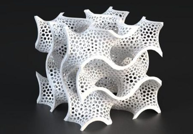
Fused Deposition Modelling (FDM) is one of the most popular 3D printing technologies for hobbyists, service bureaus and OEMs alike. From low-cost prototyping to functional parts, FDM is well-suited to a variety of applications, offering great design flexibility.
However, to achieve higher accuracy and successfully printed FDM parts, designers and engineers should consider the possibilities and limitations of designing for FDM. To help you ensure the best printing results, we’ve put together a list of the top 10 things to consider when designing for FDM.
The FDM Printing Process
Fused Deposition Modelling works by extruding a filament through a heated nozzle onto a build platform. As the material is deposited, it cools and solidifies, forming a solid layer of material. This process is repeated layer by layer until the final object is completed.
FDM typically works with a wide range of production grade thermoplastic materials, although some metal filaments can be used as well. It should also be noted that 3D-printed FDM parts will usually have a rough surface finish and therefore require some form of post-processing to achieve smoother surface.
10 Tips when Designing for FDM
1. Make your design watertight
It’s important to ensure that your FDM design is watertight, meaning that there are no holes on the surface of your 3D model. Having a watertight design can affect the printability of a part — non-watertight models cannot be 3D printed — which is why it is vital to check your design before sending it to print. RP Platform’s automation software can easily check for watertight issues and other STL file errors.
2. Support structures
Often, your FDM designs may include complex features such as steep overhangs, bridges, holes and hollow sections. To prevent build failure, these features will require support structures. It is generally easier to reduce or avoid supports, as they add time and cost to the production process, as well as leave marks after removal. Often, however, the use of support structures cannot be avoided as they enable complex geometries to be printed.
When designing parts for FDM, it is good practice to apply the 45-degree rule: features with angles less than 45 degrees must be supported to ensure a part won’t break during the printing process. Another thing to keep in mind is that walls for supports should be at least 1.2 – 1.5 mm thick to provide sufficient strength to your part.
3. Wall thickness
The minimum wall thickness for FDM parts is dictated by the filament size as well as the nozzle diameter afforded by a 3D printer. To ensure a successful print, one rule of thumb is to design walls twice the thickness of the nozzle diameter, with a minimum of 1.5-2mm thickness.
However, although thicker walls will lead to stronger parts, designing walls that are excessively thick will add to your production times and costs, and can lead to printing issues such as warping. But if your part requires thick walls, you can design cross-hatch inner structures instead of solid walls, saving material and reducing printing time.
4. Holes
The FDM process typically produces undersized holes. This means that, for example, a hole designed with a 5mm diameter may be printed with a diameter around 4.8mm. Therefore, it is best practice to design oversized holes.
It is typically recommended to increase a hole diameter by 2% to 4% for holes up to 10mm. If the accuracy of a hole diameter is critical, the hole can be 3D printed undersized and then drilled to achieve the correct diameter.
5. Threads
Best practice when designing threads is to avoid sharp edges and 90 degree angles. The recommended type of threads for FDM is 29-degree threads (also known as Acme threads) with a minimum of 0.8 mm thick of a thread. Also, keep in mind that holes for threads should be larger than 3mm to be 3D printed.
6. Minimum feature size
When designing small features for FDM, the recommended feature size for engraved details is 1mm thickness and 0.3mm depth to ensure legibility. The minimum size for columns and pins also needs to be considered during the design stage: these features should be no less than 2mm in diameter to be printable.
7. Fillets and chamfers
Since the material in FDM is heated during the printing process, temperature changes that occur can lead to deformations in your part. Luckily, with design features such as fillets and chamfers, these issues can be avoided. By adding a chamfer along the bottom edge of a part, thermal stresses can be distributed more evenly, mitigating warping and shrinkage. Adding chamfers also means that your part can also be easily removed from the build platform.
In addition to chamfers, fillets can be designed into a 3D model to reduce stresses during printing and increase strength of a part. They can also be added to the overhang surfaces greater than 45 degrees, eliminating the need for supports.
8. Part orientation
Part orientation is a vital point to consider, as it can affect the surface quality and strength of your part, as well as the number of supports needed.
Firstly, it’s important to keep in mind that upward-facing surfaces tend to have a better surface finish. Secondly, since curved and angled surfaces are often prone to stair-stepping effect (rough surface texture), you can orient such surfaces parallel to the build platform to minimise this effect. Lastly, you can eliminate the supports for holes by orienting them in a vertical direction. When parts have multiple holes in different directions, you may want to focus on blind holes first and then on holes with the smallest diameter.
FDM parts are highly anisotropic, meaning that parts will be much stronger in the XY axis than the Z plan. To ensure strength, it is advisable to design your part so that brittle features are oriented parallel to the surface.
9. Design for assembling
It often makes sense to split complex 3D model into several pieces, printed separately and then assembled together afterwards. This will not only reduce the amount of supports, simplifying the post-processing, but also speed up the printing process while saving material.
10. Infill rate
The infill rate (%) indicates how much material should fill a part when it is printed. Unless maximum strength is required, it is unusual to opt for a maximum infill for your FDM parts, since this can lead to higher material costs and slower print speeds. As the infill percentage also affects the strength of your part, it is important to consider the application of your FDM part when choosing your infill rate. Prototypes, for example, can be produced with a low infill percentage whilst end parts will typically require a higher infill percentage for greater strength.
To Sum Up
FDM is perhaps the most cost-effective technology for low-cost prototyping and functional parts. However, to get the best out of your FDM printing process, design guidelines for the FDM printing process should be considered before sending any print to production. While FDM will involve a trial and error approach to some extent, by these considerations in mind, you can reduce complexity in your processes, and significantly increase efficiency.
Source: https://amfg.ai/2018/06/14/designing-for-fdm-3d-printing-top-10-tips/