Converting a CAD-designed model into a compatible file format for 3D printing is an unavoidable step in the 3D printing process. The file format most commonly used is STL, which allows the 3D printer to interpret CAD model data and then to create the physical object. However, when an STL file is poorly exported, this can lead to a myriad of unexpected and, typically, undesired results, affecting the printability of a part. So what are the most common STL file errors that can occur after converting your files?
What is an STL file?
STL remains the most commonly used file type in additive manufacturing. When converted from CAD, the STL file represents the surface of the digital model as a mesh of triangles, which are composed of 3 elements:
1. Vertices (points)
2. Edges (lines between points)
3. Faces (surfaces between lines)
Each triangle also has a normal vector, which defines which side of a triangle faces outward. Unlike a CAD file, an STL file is an approximation of the original design, and contains the information of both the inside and outside of a part.
The top 5 STL file errors
A correct STL-based model is characterised by closed and connected triangles that don’t overlap and where every edge is part of two triangles. However, when converting from CAD to STL, errors can frequently arise due to a fault in the conversion. These errors can directly impact whether you’ll be able to 3D print your part.
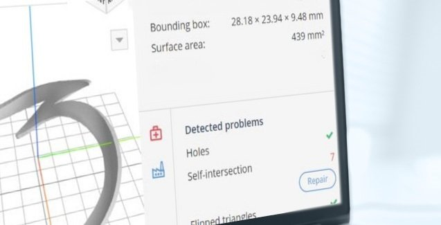
1. Holes or gaps in a mesh
One of the most common errors leading to printing failures is missing triangles. This occurs when the adjacent triangles fail to share two common vertices. If this error is overlooked, the printer will not be able to correctly print the design. This is why it’s crucial to make the design in STL file manifold or, as it’s also known, watertight – which means that there mustn’t be any gaps on the surface.
2. Flipped(Inverted) normals
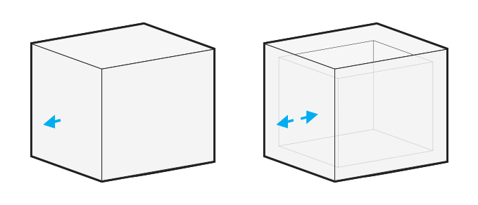
Each triangle in the mesh has a normal vector, which points out to the outer side of a triangle. Normals tell the printer which way to add the material. Occasionally, the normal vector faces the reverse direction and this can lead to confusion during the printing process. When the designed model has a flipped normal, a 3D printer has difficulties in identifying the inside and the outside of the model, and so the model cannot be accurately sliced and printed.
3. Intersecting and overlapping triangles
This error occurs when two surfaces overlap or cross one another due to the complexity of the internal geometry. While it typically doesn’t take too much effort to repair such an error, if it isn’t corrected, this will inevitably add time and cost to the process, as the model will require more material. To avoid a failed print, you will need to remove or unify these triangles with file repair software.
4. Bad edges
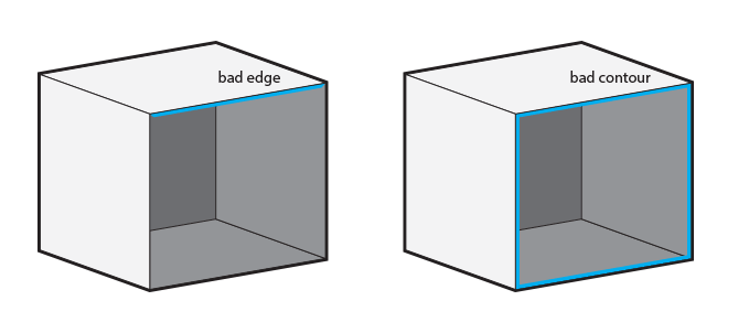 The problem of bad edges is encountered when the edges of triangles are not properly connected to each other, creating holes and bad contours. Bad edges result in a non-manifold design, which means that the digital model isn’t printable. Patching and blending bad edges with the dedicated software tools can help to repair the file and will allow you to print a high-quality object.
5. Noise shells
Shells are the outer layers of a print on the outside of the model. The higher the number of shells, the denser outside walls of the printed part. However, when a shell gets too small, it becomes redundant and serves little purpose. Such shells are called “noise shells” and, although they can be easily dealt with by flipping inverted triangles.
Luckily, AMFG’s AM automation software can automatically analyse and repair the most common of file errors – so you don’t have to.
Other considerations
Aside from the most common STL file errors, it is still important to take the time to carefully inspect your part’s design before sending a file to be 3D printed.
Checking the wall thickness of your part is vital to achieve the balance between printing part that is strong enough while saving as much material as possible. Thin walls mean that your model may not be able to be printed or will be too fragile and easily break. Walls that are too thick on the other hand cause too much internal stress which can lead to cracking and breakage. However, with AMFG’s part preparation software you can easily analyse the wall thickness of your part.
Another factor to consider is the size of your STL file, as you may end up with a file size much larger than required due to the excessive number of triangles in the STL mesh. It’s important to remember that the more triangles your file contains, the harder it will be for the printer to process and slice. While this will not necessarily result in a failed print, a very large file size will cause difficulties in process management – so in this case, triangle reduction will be necessary.
Source: https://amfg.ai/2018/04/19/top-5-stl-file-errors-you-should-know/