Liquid injection molding (LIM) is an industrial fabrication process that molds materials into a broad range of components and products. Unlike the standard reaction injection molding process, which relies on pressurized impingement mixing, liquid injection molding uses a mechanical mixing process that focuses mainly on liquid silicone rubber (LSR) and similar elastomeric materials.
Injection molding of High Consistency Rubber (HCR), the oldest form of producing silicone rubber parts, continues in widespread practice around the globe. Nonetheless, the liquid injection molding process has gained a reputation as the preferred process among many manufacturers of rubber parts, because of its superior end-of-product performance – durability, tensile strength, flexibility, and accuracy. In addition, the liquid injection molding process facilitates high levels of automation, and the ability for 24/7 production.
One of the primary keys to the flexibility of liquid injection molding has to do with the unique properties of liquid silicone materials. The material has superior heat and flame resistance characteristics, withstanding temperatures over 250°C, and as low as of -90°C. In addition, silicone material provides unparalleled formability qualities, which allows for transparency or coloring of the finished product.
Just about every industry imaginable has discovered the opportunities presented in the liquid injection molding process, including the following:
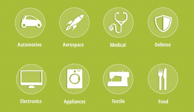
The thermal, chemical, and electrical resistance of LSR allows for a broad range of products, including components seals, o-rings, isolators, valves, cables, electronic components, and other parts. Liquid silicone rubber maintains its integrity under the sterilization. The biocompatible features of LSR also make it safe for products that have contact with the skin.
HOW THE LIQUID SILICONE INJECTION MOLDING PROCESS WORKS
The materials commonly used in the LIM process are silicones and acrylics. The process requires the use of a spring-loaded pin nozzle to help prevent the machine hardware from becoming clogged with materials. The spring-loaded mechanism permits the injection pressure to be higher than the pressure of the extruder barrel, which keeps the channel unblocked.
Utilizing a pump the LIM method brings together an apportioned mixing and dispensing of LSR. One plunger holds the base forming plastic, which can be strengthened with additives and fibers. The other plunger contains the catalyst. Each will be pumped in a 1:1 ratio into a static mixer, which triggers the mixing reaction.
The liquid mixture is then injected into a sealed mold where it is heated at temperatures from 180 to 200 C, or 355 to 390 F. It starts out as a fluid and is then heated within the mold to initiate curing. Once it hardens, the molding machine ejects the nearly finished part.
Thermoplastics operate in reverse; the materials are heated in the injection barrel to their melting point and then cooled in the mold. Many manufacturers use computer-aided design (CAD) tools to make the LIM process more efficient. CAD allows them to run simulations to determine the most cost-efficient and effective processing regiment and conditions, evaluate results, and check integrated components.
In addition, thermal imaging technology can help pinpoint costly production mistakes, especially molding defects and design irregularities.
LIQUID INJECTION MOLDING MACHINES
Liquid silicon rubber material comes in a kit that consists of two components: “A” and “B”.
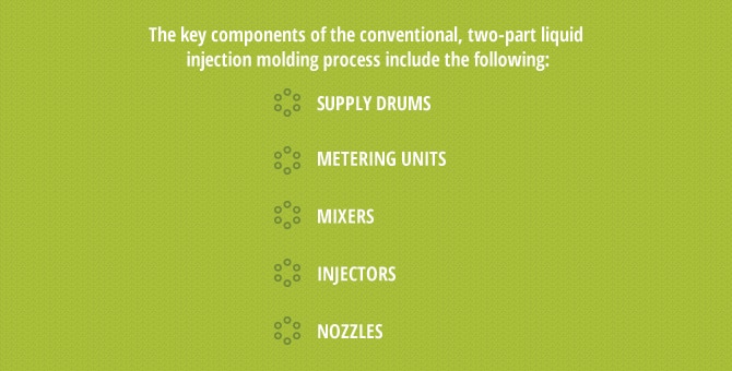
The key components of the conventional, two-part liquid injection molding process include the following:
- Supply drums: The plungers, or liquid silicone supply containers, connect to the pumping system. Many two-container setups include a third container for pigment.
- Metering units: The metering device pumps the two liquid materials in predetermined ratios, which ensures a concurrent release at a steady ratio.
- Mixers: Once the liquid forming materials pass through the metering unit, a static mixer combines the materials. The blended material is pressurized and pushed into the mold.
- Injectors: This device moves the LSR forming material into the pumping mechanism under pressurized force. The machine operator has the capability to adjust the pressure, as well as the injection rate. This parameter differs according to the project specifications.
- Nozzles: The liquid compound flows into the mold through a nozzle that has an automatic shut-off valve. This valve prevents the mixture from leaking or the mold from overfilling.
In an ideal production environment, the basic liquid injection molding machine should be as lean and as compact as possible. Secondary devices should be configured to address the needs of a particular project.
EFFECTIVE LIM DESIGN
As with any manufacturing process, the LSR molding process starts with proper part design. Those familiar with designing parts for injection molding should find the design elements of the silicone rubber injection molding process to be alike. However, LSR has a very high shrink rate and the material has a tendency to flash very easily during molding. The designer can mitigate these issues by planning the correct tolerances and assimilating extra elements into the mold design to help reduce flash.
The liquid molding process offers greater freedom to part designers in comparison to conventional injection molding processes. LIM parts do not require the use of high heat and pressure to melt the material, which allows for a consistent flow of LSR into the mold. As a result, the designer has more flexibility and uniform part geometry.
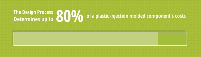
The Massachusetts Institute of Technology states that the design process determines up to 80% of a plastic injection molded component’s costs. It also has an impact on quality, reliability, functionality, serviceability, and manufacturability. The design also has a bearing on time to market, and it plays a crucial role as a driver of competitive advantage.
Designing plastic components involves a complicated task, which encompasses a variety of factors associated with the requirements of the part. It entails asking and answering a series of questions, including:
- How the part will be used?
- How does the part work with other components?
- What are the weight, structure, impact, and load requirements?
- Are there any environmental conditions that must be considered?
- What are the cosmetic requirements?
- Does the part have any unusual characteristics?
It’s important to consider the design parameters for your LIM program. Below are nine considerations.
1. Maximum Part Size
The following are approximate part sizes:
- 5 inches-by-5 inches-by 2 inches (127-mm-by-127-mm-by-50mm)
- No deeper than 2 inches (50 mm) from any parting line
- Maximum projected mold area of 17.6 square inches (113.55 sq cm)
- Maximum part volume of 4 cubic inches (65.55 cc)
- Wall and Rib Thicknesses
LSR has the capability to fill a thin wall section with fewer challenges. Parts can have a wall as thin as 0.010 in. (0.25 mm.), depending on the size of the wall and the location of contiguous thicker sections. The only limitation is whether the thin detail can be milled into the mold or ejected from the mold without damaging the part. Rib thickness should be approximately 0.5 to 1.0 times the thickness of the adjacent walls. The radius of inside fillets should be near the thickness of the wall because smaller or larger radii may cause porosity.
- Mass Reduction and Uniform Wall Thickness
Although liquid silicone rubber has superior ability to accommodate deviations in wall section, and it has almost no sink, the same rules for standard plastic part design apply.
- Parting Lines
Determining the location of the parting lines is one of the initial steps in the tooling process. To make the process easier, minimize parting lines to produce cleaner parts and save time.
- Undercuts
One of the key benefits of LSR molding has to do with the ability to create parts with undercuts. Most undercuts can be removed with minimal effort by the press operator or with mechanical help. Then, each part gets evaluated on a case-by-case basis for viability.
- Part Ejection
LSR molding does not require ejector pins like the standard practice with thermoplastic molds. When designing the part, the entire part is retained on one half of the mold when it is opened at the end of the molding cycle. Under ideal conditions, the part features will rise above the parting line surface, which makes the part easier to demold.
- Draft
For the ease of the manufacturing process, LSR parts require draft similar to plastic injection molding. While 1 degree draft is commonly used, per inch (25.4mm.) of depth, on shallow components zero draft can be used occasionally. If mold construction allows, the inherent characteristics of LSR allows more flexibility with draft rules than it does with thermoplastics.
- Gating and Venting
The shear thinning characteristics of LSR parts require small gates compared to injection-molded parts. Although it’s not an absolute rule with liquid silicone rubber, a gate should feed the thickest cross-section of the component, like thermoplastics. Most LSR gates use some type of edge gate. Gates typically leaves a mark or blemish. Place gates on a surface that is not dimensionally or aesthetically important or provide a recess for gating.
- Expected Tolerances
Well-designed parts usually have a linear tolerance of 0.025 in/in (0.025 mm/mm). You will also need to consider flash allowance.
In addition to optimizing the design of a component, it is also crucial to select the right material for LIM programs.
MATERIALS SELECTION FOR LIM PROGRAMS
LSR has been used in Europe for a number of years. Because of a lack of in-house expertise, many manufacturers in North American are only now beginning to understand and appreciate the performance advantages LSR has over other rubbers and thermoplastics.
One of the most critical factors to consider for a successful silicone molding program has to do with material selection. Standard or general-purpose grade LSR does not have a high fill of silica, which makes it appropriate for applications that require basic physical characteristics. Advances in LSR material have led to significant improvements in the product beyond attributes, such as thermal stability, rubber-like qualities, and resistance to aging.
The addition of additives and other fillers give LSR the capacity to endure higher temperatures, oil, and other fluid environments. With the addition of phenyl units, LSR has greater capabilities in low-temperature settings. Adding phenyl fluid reduces the coefficient of friction, creating a part with a slippery surface as the fluid gradually bleeds out. Some varieties of LSR impart low friction chemically, which eliminates the need for fluid to bleed to the surface of the part.
The latest LSR technologies have a grade of self-adhesive material suitable for hard/soft overmolding applications or two-shot molding. This has eliminated the need to apply a separate primer (and another tool) to bond LSR to many commonly used thermoplastic. It also produces cooling cycles that closely adhere to the typical cooling cycle for the thermoplastic, and it permits the in-mold bonding of the liquid silicone rubber to a thermoplastic.
Molders can select from many different types and grades of liquid silicone rubber, from tacky to soft touch, as well as an array of hardnesses. It is important for engineers to perform analyses to ensure that the material has chemical compatibility and wear resistance. It must also meet environmental and performance criteria as outlined in the program.
PROTOTYPING
Before paying out for full production tooling, you may want to see an actual sample of the part in order to help ensure that the scale-up from prototype to production is a seamless transition. Prototypes can be crucial to the development process of liquid injection molded parts, because it can save you both time and money by making it possible to evaluate a part’s form, fit, and functionality.
The primary objective during the prototype stage involves the identification of any part performance or production process issues prior to the full-scale manufacturing phase.
The technologies for plastic injection molding prototyping range from traditional CNC machining to various full-range, additive manufacturing rapid prototyping technologies, including:
- Traditional CNC machining
- 3D printing
3D printing includes Stereolithography (SLA), which works well for evaluating part sizing, fit, and function, as well as providing a finished part for marketing campaigns. Fused Deposition Modeling (FDM) prototypes provide conceptual and engineering models, as well as functional testing capabilities.
LSR INSPECTION & TESTING PROTOCOLS
To verify that the quality control standards for Silicon Rubber Liquid are met, and that the component material can carry out its purpose, the tensile properties of thermoset rubbers and thermoplastic elastomers must be tested (measured).
The testing standard is ASTM D412, which consists of two test methods: A and B. Method A, the most prevalent testing approach for silicone rubber liquid, tests a dumbbell-shaped sample on a universal testing machine, which has standard clamps. Method B employs a ring specimen that requires a special clamping mechanism.
There is also a variety of inspection and testing equipment used in proprietary internal manufacturing processes, including:
- Elastomeric physical properties testing
- Elastomeric rheometer
- OGP Flash Inspection System
- Video microspoe
A testing program should also include the sampling of parts, materials, and process to obtain qualitative data.
PILOT PRODUCTION
When the tooling has been completed, you can run the new product design through the pilot production process phase so that you can look at samples of the part.
This is where you can:
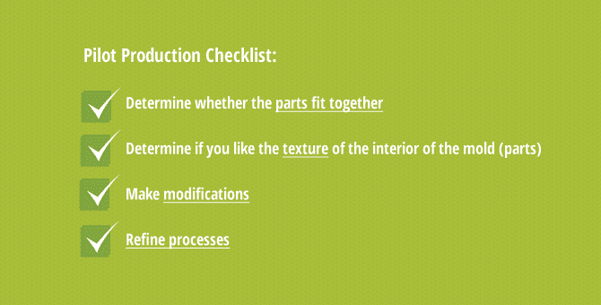
You can also work out other bugs and modifications to the mold, and refine processes if necessary. Once you have the tooling and processes refined, you can easily fine-tune materials and color without any problem. The attention given to the official pilot production stage will have a direct impact on the efficiency and effectiveness of the manufacturing process. Not only will it reduce manufacturing costs, but it can also assist in reducing the time-to-market and delivering the best product possible.
FULL-SCALE PRODUCTION
Most original manufacturers do not have the in-house staff necessary to successfully execute an LSR program. Consequently, many end up online in search of a vendor. Many companies have purchased machines and invested time and money learning about LSR injection molding technology in order to move into the silicone segment of the market. However, thermoplastic experience cannot substitute for LSR expertise in part design, mold design, and the manufacturing process because of the unique challenges of the liquid injection molding process.
For instance, silicone has stringent tooling standards, which can mean numerous challenges with gating, venting, and the increased risk of inadvertently damaging components. Methods also vary from supplier to supplier. Some vendors have a manual process while others use flash-free tooling and an automated molding process. Each method has its advantages and disadvantages, but you will need to look at it in terms of the additional variables, including employees with the necessary knowledge and skill set and increased costs in an already capital intensive and complicated process.
EVALUATION & QUALITY CONTROL
The review process follows ISO 9001:2015 quality standards protocol to assure that all product output meets the criteria determined by the customers’ product specifications and delivery conditions, as well as in-house engineers and industry best practices.
To understand the processes and products, the evaluation and quality control program depends on a data-driven approach and continuous assessment based on proven, scientific concepts and best practices.
The quality control program should include:
- Document and data control to ensure the most current, accurate information.
- Inventory control and identification of materials.
- Process control to get part production right the first time.
- Inspection and testing of parts.
- Non-conforming controls to avoid shipping inferior-quality parts.
- Handling, warehousing, packaging, and preservation.
The idea is to fully document all stages of material procurement, product manufacturing, and distribution.