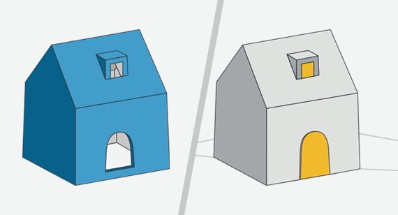
To take a closer look at shut-offs—a design element that allows engineers to solve difficult tooling and design issues—let’s consider the injection molding of a box-like part, as seen in Figures 1A and 1B. The box looks like an A-frame house with four vertical walls and a roof. On one of the vertical walls there is a cut out that would resemble a door and on the roof there is a dormer with a window.
The A-side is the exterior of our box (1A) and the B-side is the interior core (1B). In order to create the door and dormer window, the faces of the mold must slide past each other until the mold closes where they create a seal which creates a hole in your part. These are the shut-offs, shown in yellow in Figure 1B.
Shut-offs Help Create Part Features
Shut-offs in straight-pull molds will allow you to design many different features that fall in to three basic categories: Holes, hooks, and long through holes without the use of side-actions (cams).
In the illustrations shown in this tip, you will see several design examples. Let’s first go back to the box-like “house” part example. Figure 1A shows the door in our box, or a hole in the wall. The door is formed by a pad that lives on the B-side core (Figure 1B). The pad is the same thickness as the wall section of the part and seals against the vertical wall of the A-side cavity. If this seal is damaged or wears too aggressively, the plastic will sneak past the seal and create flash. The dormer window on the roof of the part is formed the same way, but shows this form of shut off surrounded by plastic.
What solves this potential seal problem? The use of draft.
Shut-offs require greater draft to reduce the amount of wear on the mold and form a better seal under clamping force during molding. A minimum draft of 3 degrees allows greater clearance for the sealing faces on opposite sides of the mold to pass by one another without the risk of gouging and wear.
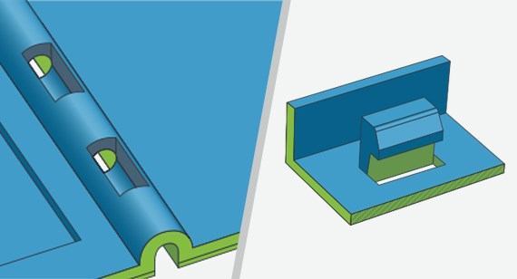
In the next set of illustrations, Figure 2A shows a through hole across a 4 inch-wide part. With side-action pull-length limitations, or to try to reduce the overall cost of the mold by removing the need for a side-action, you need to be creative at times. Creating a segmented trough on the A-side (in green) and a corresponding segmented trough on the B-side (in blue) creates a series of shut offs that form a through hole across the entire part. This works especially well for hinges, bolt holes, pivot pins, etc.
Hooks and Snap Features
Figure 2B is the big one. Undercuts, most notably snap features, tend to be no-nos in the world of simple straight-pull rapid injection molds. Snap features would typically need a pickout insert or a lifter mechanism to form the undercut–these would add to the cost and lead time to produce the tool. A pass-through core (square in this instance) is a standing block of aluminum on one side of the mold that mates to a pocket in the opposite side of the mold. One face of the block forms the inside leg of the hook while the other three faces of the block are drafted at 3 degrees and create shut offs against the mating sides in the pocket. Once the mold is opened and the part is ejected, you will have a hook that snaps to your mating part.
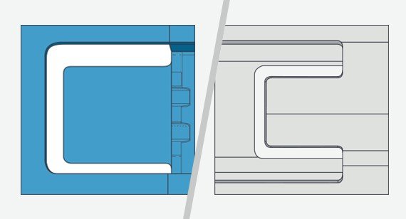
The final set of illustrations, Figures 3A and 3B, include a top down view of a clip. This image shows the space in between the clip and the pull-through core to build the shut-off. This component part is just a small section of a much larger complex part.
Shut-offs are powerful tools that allow creative designers and engineers to solve difficult tooling and design issues using drafted walls sealing against drafted walls, eliminating the need for post-molding machining or the need to remove functional geometry.
As always, feel free to contact an applications engineer with any questions, at 877-479-3680 or customerservice@protolabs.com.