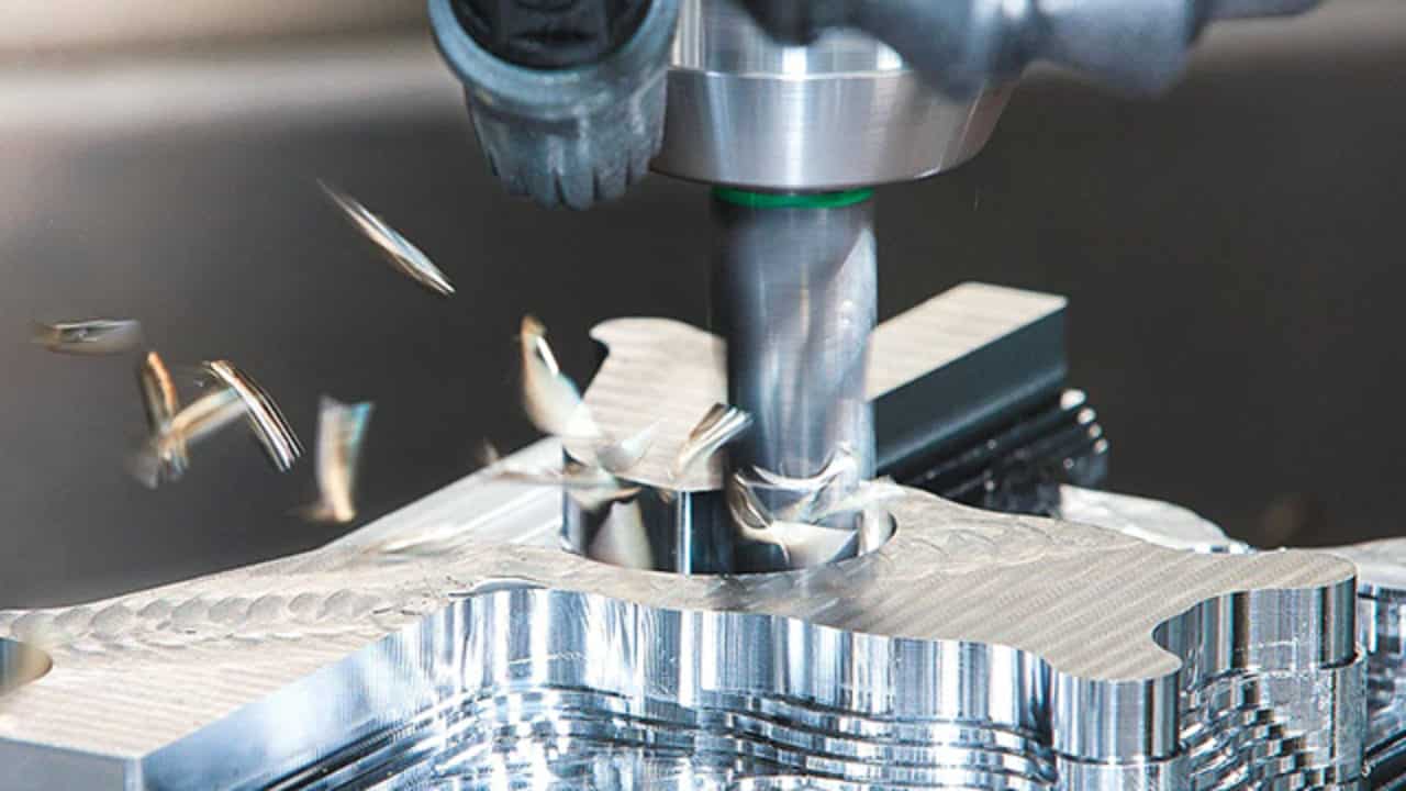
How does CNC machining differ from traditional machining?
In traditional machining, a skilled machinist operates a machine, removing or forming metal. This is done according to specifications provided by designers and engineers, usually through an engineering drawing or blueprint. They use turn wheels, dials, switches, chucks, vices, and a variety of cutting tools made of hardened steel, carbide, and industrial diamond then use measurement instruments to ensure all of the dimensions are correct.
CNC machining performs the same function as traditional machining — metal cutting, drilling, milling, boring, grinding, and other metal forming and removal functions — but it uses computer numerical control rather than manual control by a machinist. It is automated, driven by code, and developed by programmers. It is about as precise the first time of cutting as the 500th. Widely used in digital manufacturing (and sometimes in low-volume production runs), it can be revised and altered for modifications and different materials.
This type of machining is much more precise and has largely superseded traditional machining (though not entirely) in manufacturing, fabrication, and industrial production. It uses mathematical coordinates and the power of computing to achieve the same end, with the greatest accuracy. Specifically, computer numerical control uses Cartesian coordinates. These are spatial coordinates — in several dimensions — using coordinates and axes. The automation of cutting tool machines controls its cutting, boring, drilling, or other operation using the numerical control of a computer that reads the coordinates. These coordinates were designated by engineers in the product’s digital drawing and design.
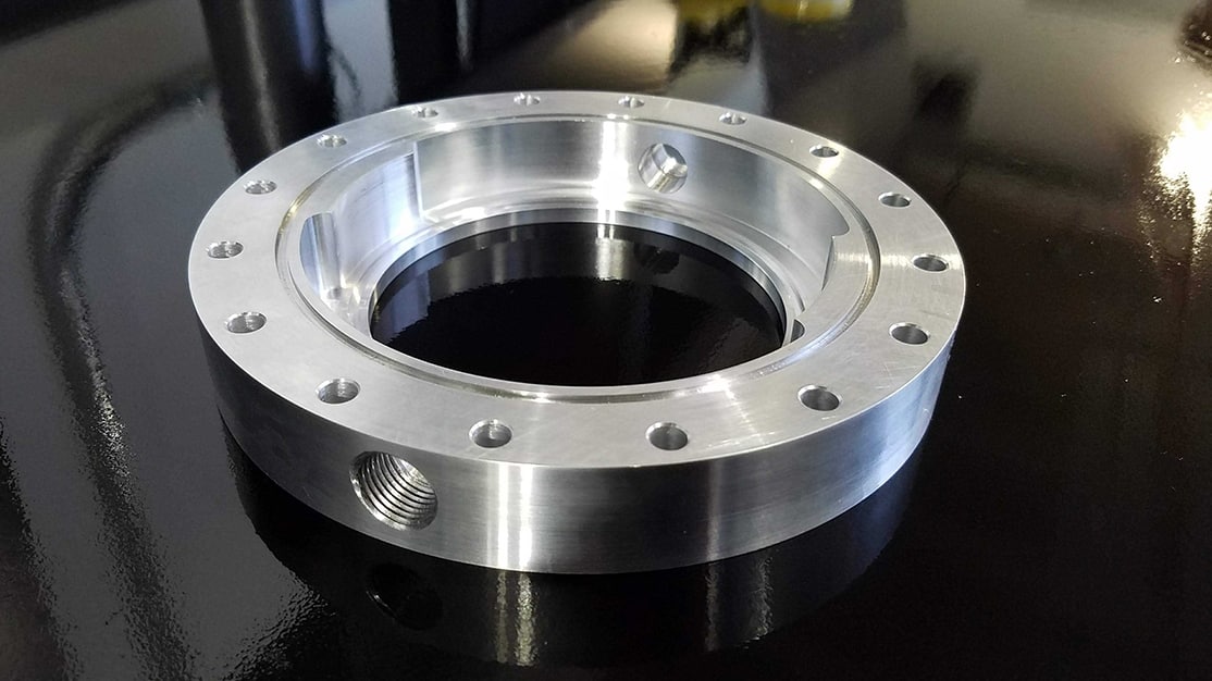
What is the CNC machining process?
CNC machining uses subtractive processes, which means feedstock is machined to final form by subtracting and removing material. Holes are drilled, lots and pathways are bored, and metal stock is shaped into new materials with varying tapers, diameters, and shapes.
For subtractive manufacturing, shapes are achieved by the subtraction of material. This contrasts with other types such as additive manufacturing — where materials are added, layered, and deformed to a specified shape. It also contrasts with injection molding where the material is injected in a different state of matter, using a mold, and formed to a specified shape.
CNC machining is versatile — and can be used with various materials, including metals, plastics, wood, glass, foam, and other composite materials. This versatility has helped make CNC machining a popular choice across industries, enabling designers and engineers to fabricate products with efficiency and precision.
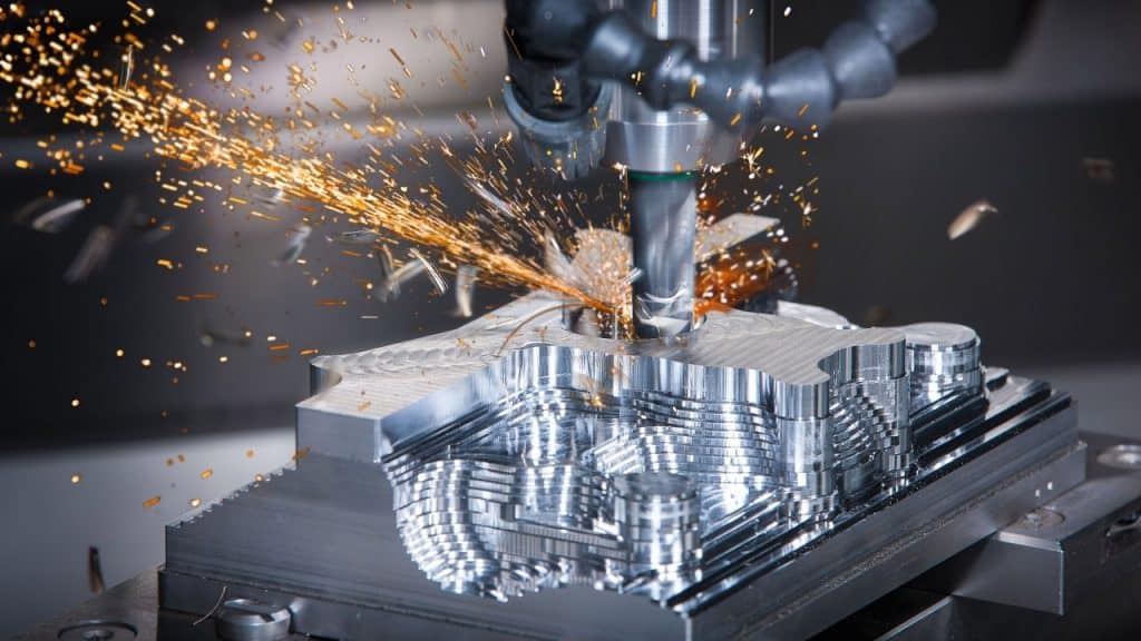
Pros: Timely, reliable, accurate and robust
CNC milling and turning are highly accurate and repeatable processes. Tight tolerances between +/-0.001″ – 0.005″ can be achieved, depending on specifications. Machines can be programmed to reliably run for 24 hours, 7 days a week if necessary, so CNC milling is a good way of getting parts produced on demand.
Using standard tooling, CNC machining is particularly valuable for creating custom, one-off parts, i.e. for replacing legacy components or delivering a specialized upgrade to a customer. It is also conceivable to scale single-part production to runs exceeding 10,000 units. Depending on the unit number, size, and complexity, the turnaround for components can be as short as one day. With shipping and delivery, deadlines can be met within a week.
Another primary advantage of CNC technology is the achievable mechanical properties. By cutting away from bulk material, rather than thermally transforming it as in injection-molding or additive manufacturing, all desirable mechanical properties of the metal or plastic of choice are retained. More than 50 industrial-grade metals, alloys, and plastics can be machined using CNC milling and turning. This selection includes aluminum, brass, bronze, titanium, stainless steel, PEEK, ABS, and zinc. The only material requirement for CNC machining is that the part has an adequate hardness to be fixtured and cut.

Pros: Costs that Work for You
To achieve the most cost-effective CNC machined parts, larger production runs are recommended to spread the cost of machine setup. Unit price decreases incrementally when CNC machining up to volumes in the thousands where it plateaus. Structured batch production and shipments of CNC parts can help mitigate wastage or inventory costs.
Of all the various machine configurations, 3-axis CNC milling, the simplest setup, is generally the cheapest method of making uncomplicated parts with high tolerances. CNC turning on a lathe is also a highly cost-competitive process when cylindrical workpieces like threaded rods and shaft couplings are required. Typically, a lathe would cost 15% less than the 3-axis machine for a similar part.
With 5-axis CNC machining, the options are split into two configurations: indexed 5-axis CNC milling and continuous 5-axis CNC milling. In indexed 5-axis CNC milling, the workpiece is automatically rotated to give tools more access to mill features. The extra two directions of movement are done between milling steps without removing the part from its fixture. The difference with continuous 5-axis CNC milling is that the machine can simultaneously move in all directions as the workpiece is cut. Both processes eliminate the added cost and potential margin for human error that comes with manually repositioning a workpiece. Due to these benefits, 5-axis machining is the best solution for complex components.
In comparison to “basic” 3-axis CNC mills, 5-axis machining comes at an increased expense, with indexed 5-axis CNC milling being the cheaper of the two. Continuous 5-axis CNC milling typically costs over 20% higher than an indexed 5-axis machine, and about double that of a standard 3-axis mill.
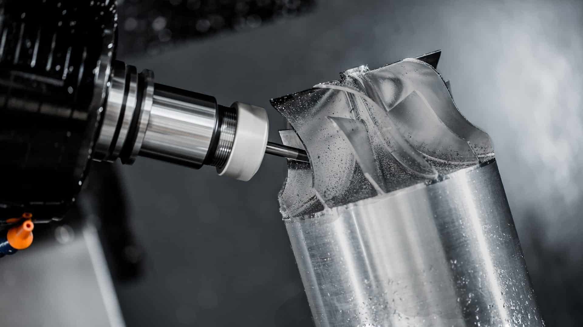
Cons: Cost of Geometric Complexity
One trade-off when taking advantage of the high performance of CNC machining is that geometric complexity comes at a cost. Simple, chunky parts are the best designs for CNC milling and turning. There will always be some design limitations due to tool access, although the degree of this effect is relative to the number of axes on the machine. In other words, the more axes used, the more complex the features can be achieved.
Another trade-off is that start-up costs for CNC machining can be expensive. It is necessary to have a trained professional perform the setup, tool loading, and programming on CNC mills and lathes. Luckily this cost is fixed, so by taking advantage of the same setup for multiple parts, it becomes more economical. Saving money is also achieved by keeping part repositioning to a minimum. Machining at 5-axis and above can sometimes be more economical on multi-faceted geometries because it eliminates the need to manually reposition the part.
Wire EDM method of machining can be slow and expensive relative to other processes, and the range of materials that can be used is shortened as they must be electrically conductive.
Key Checklist for Quality Design
CNC machining is the manufacturing method of choice when you need simple parts with tight tolerances, excellent mechanical properties, and scalable low volume production. To achieve the highest impact from each of these strengths, there are several key factors that you should consider during the design process.
Your decisions will vary depending on the technology used, i.e. 3-axis, 4-axis or 5-axis milling, and mill orientation, i.e. horizontal or vertical. Every variant, however, will circle back to four key questions:
- What size and shape drill bit can I use?
- Can this tool access the feature that I want to mill?
- How much vibration will this make (at the cost of precision)?
- How will the heat of the bit affect the material I am working with?
With these four questions in mind, here are seven basic rules to follow for effective CNC machined part design. Tip: A chart of standard bit sizes and diameters for reference throughout this article can be found here.
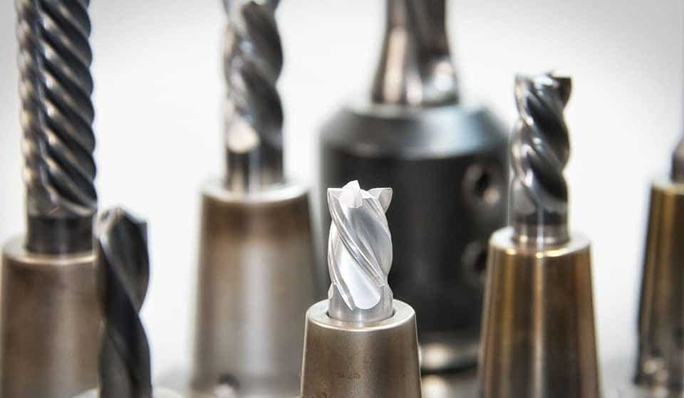
7 Rules of CNC Machining
Rule 1: All roads lead to radii
As the majority of drill bits are cylindrical by design, this means any internal cuts you make will also create a curved corner/edge, also known as a fillet. When designing a part containing internal fillets, “the bigger the better” is a good rule to follow. The resulting corner will be half the diameter of the tool used.
Use a non-standard radius, e.g. 1.25 mm rather than 1 mm, to give a tool clearance to cut the corner. Where possible, design using a different wall and floor radii too so the same tool can be used throughout.
The exact measurement for internal corners will be relative to the depth of the cavity being machined. When inserting internal corners and edges, account for a radius of more than one third the depth of the cavity.
Rule 2: Undercut for right angles
To create right angles in a CNC machined part, it is better to add undercuts to the design rather than attempting to reduce the radius of your corners for a similar effect. To avoid the added cost of custom tooling, design an undercut with a standard dimension, i.e. 3 mm to 40 mm wide in whole mm increments. Due to the shape of tools used, keep undercuts shallow where possible. The maximum achievable depth of undercutting tools will be double the width of the head.
Rule 3: Fillets give you cavities
Cavity/pocket depth is typically relative to the diameter of the tool used to make internal fillets. As a guide, the pocket depth should be up to 3 – 4 times the tool diameter. Any deeper than 6 times the tool diameter will require a larger tool. This will result in sacrifices to the radius of your corners.
Cavity width should also be considered when machining a pocket. Keeping depth to a maximum of 4 times the width is a good guide measurement.
Rule 4: Tall features, bad vibrations
As with the depth of cavities and pockets, the maximum height for tall features is up to 4 times the feature’s width. The taller a feature, the more prone to vibration it is, reducing the machined precision of your part.
Rule 5: Avoid thin walls
Generally speaking, it is better to have thicker walls in the design of your part. As with tall walls, vibrations increase when producing thin features. When machining plastics, heat also has to be taken into consideration. Thinner walls will be more susceptible to softening and warping due to the friction of the tool head.
As a guide, between 1.0 and 1.5 mm is an appropriate minimum thickness for plastic walls. Minimum walls within the range of 0.5 mm and 0.8 mm are possible in metal parts. Walls should be thicker if they are supporting or taller to avoid vibration and chatter.
Rule 6: Stick to the standards when making holes
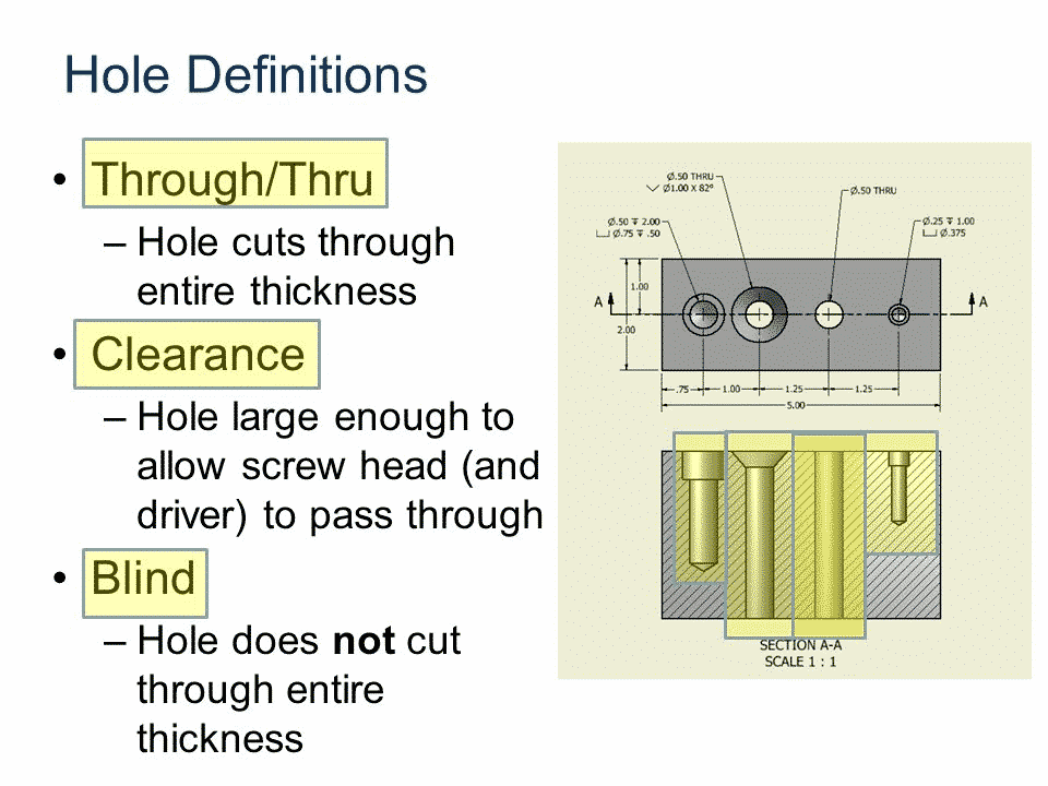
There are two types of holes to choose from in CNC milling: blind holes and through holes. No matter which of these types is chosen, the recommended depth and diameter are the same. Hole diameter should correlate to standard drill bit sizes from 25.5 mm (over 1 mm diameter) and above. The maximum hole depth relies on the nominal diameter of a hole. It is common to create a hole depth equal to 10 times the nominal diameter of a hole.
Rule 7: Stick to the standards for threads
Sticking to standard sizes is also important when creating threads. The larger the thread, the easier it is to the machine. Length should be kept to a maximum of 3 times the nominal diameter of a hole. Avoid extra costs by sticking to off-the-shelf thread sizes in your parts.
Design for CNC Machining Checklist
| Feature | Rule |
|---|---|
| Internal corners/edges | Radius ≥ one third cavity depth |
| Undercuts | Design using standard dimensions: 3 mm to 40 mm |
| Pockets | Guide maximum depth is 4 x the width |
| Tall features | Guide maximum height is 4 x the width |
| Walls | Minimum wall width for plastic: 1.0 – 1.5 mm, Metal: 0.5 mm – 0.8 mm |
| Holes | Depth should be kept within 10 x the nominal diameter of the hole |
| Threads | Length should be kept within 3 x the nominal diameter of the hole |
CNC Machining Materials
Aluminum
Key properties: Aluminum is highly regarded for its strength-to-weight ratio and corrosion resistance. It also exhibits good thermal and electrical conductivity.
Brass, Bronze, and Copper
Key properties: Pure copper is a soft and malleable metal with very high thermal and electrical conductivity. Both brass and bronze are alloys of copper. Brass is a combination of copper and zinc, and bronze is mainly copper with tin. In general, brass is valued for its machinability and high strength retention. Bronze has low-friction properties with high resistance to corrosion. Brass, bronze and copper are all often selected for their aesthetic appearance.
Steel
Key properties: Arguably offering the widest variety of CNC machining materials, steel is available as stainless, alloy, tool and mild varieties. Generally speaking, steels have good mechanical properties and are easy to machine.
Titanium
Key properties: Although heavier than aluminum (but still lighter than steel), titanium is also known for its exceptional weight-to-strength ratio. Due to its hardness, many varieties of titanium are deemed difficult to machine.
Zinc
Key properties: Zinc is not commonly used in CNC machining because most varieties are too brittle for the process. In some particular forms, the material becomes easy to work and is readily treatable.
Plastics
Key properties: Lightweight and strong, some industrial plastics can be considered as low-cost replacements for metal parts. Incredibly versatile, plastics have wide-reaching applications across all industries.