You’ve seen the routine on TV—good cop, bad cop. Bad Cop is brittle, scary, and liable to snap at any moment. You wouldn’t want to add to his stress level by not telling him what he wants to know. Good Cop, on the other hand, is flexible and easy-going.
Molded-in clips on plastic parts cover much the same range. Their job subjects them to a certain amount of deflection as they move out of position and then back again. Often, they face the same deflection over and over again. Good clips—that is, well-designed clips—handle the stress with ease, recovering fully after each deflection and remaining none the worse for wear. Bad ones that are poorly designed often break immediately or fail to fully recover, become weakened and eventually break. Unlike TV cops, however, good and bad clips do not work in teams. Each works alone (or fails to work, as the case may be).
One crucial decision that contributes to the effectiveness of a clip is the choice of material. Obviously, a spring clip requires some flexibility. If for some reason, the resin in which a part is molded cannot be as flexible as you’d like, other factors must compensate for that inflexibility.

Stress and Flexibility on Plastic Clips
There are three factors affecting the stress caused by flexing a clip. The first is the length of the flexing arm. A longer arm creates less stress for a given deflection of the end.
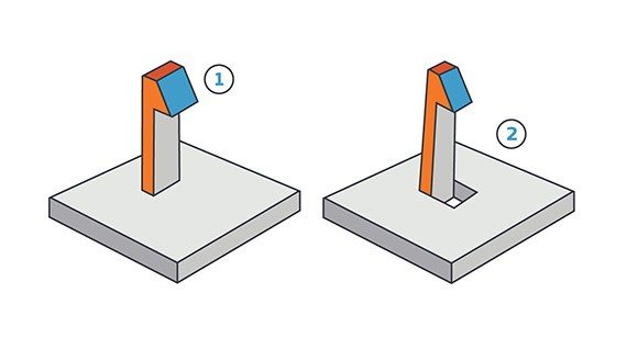
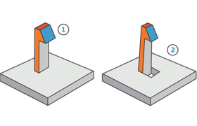
If your design limits the length of the clip’s flexing arm, you can increase the arm’s effective length in several ways. One is to loop or coil the arm, allowing more functional length in less space. Another is to notch the wall to which the clip is attached, making the notched part of the wall, effectively, part of the clip arm. Similarly, you can design the wall itself to flex slightly without being notched, accomplishing the same result.
The second way to reduce stress on the clip is to limit the size of the hook at the end of the arm. Obviously, the hook must be large enough to do its job, but the smaller it is, the less the arm has to move as the hook engages. Finally, be aware of features such as sharp corners that can concentrate stress over small areas. Pay special attention to the base of the clip where rounded corners and fillets can be used to distribute stress just as they are used to strengthen other features in a molded part.
Considering Draft
One other issue that should always be considered in designing a clip is draft. Because clips are long and narrow, it is particularly important that they be properly drafted along their lengths. In addition to easing ejection of the part from the mold, this also strengthens the clip at its base, the location of the maximum bending moment. And don’t forget to make the through-hole at the base of the clip generously larger than the clip-head. This allows clearance for the core in the mold which forms the underside of the clip-head. If you can visualize this core, try to give it a minimum of 3 degrees of draft and make its length no more than 8 times its thickness.
Some CAD packages include simple finite element analysis (FEA) programs. If you use a lot of spring clips, consider buying a separate, more sophisticated FEA package; it could save you lots of time and money.
As always, feel free to contact an applications engineer at FacFox with any questions, at info@facfox.com.
